


In the landscape of software architecture, translating abstract requirements into concrete visual models is a critical skill. Among the behavioral diagrams in the Unified Modeling Language, the Interaction Overview Diagram serves a unique purpose. It bridges the gap between high-level activity flows and detailed interaction specifics. This guide provides an authoritative breakdown of how to construct these diagrams effectively, ensuring clarity, maintainability, and precision in your design documentation.
🧠 Understanding the Interaction Overview Diagram
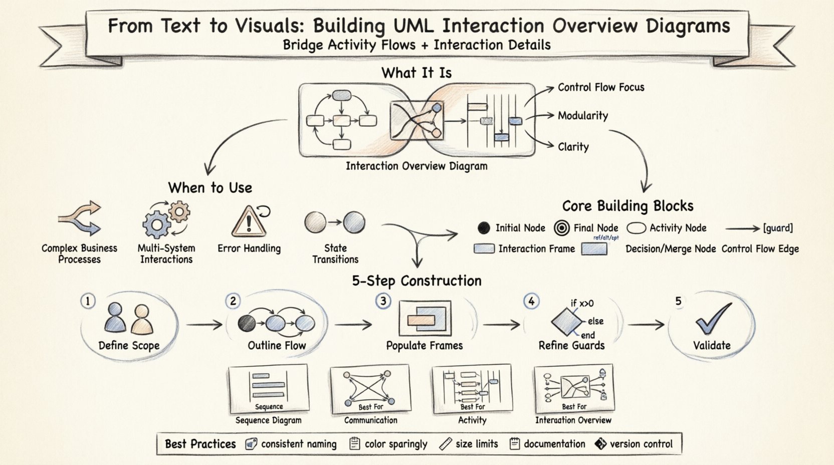
At its core, this diagram type combines elements of activity diagrams and interaction diagrams. While a standard sequence diagram focuses on a single interaction flow between objects, an interaction overview diagram manages the control flow between multiple interaction fragments. It acts as a master map, showing how different sequences of events connect, branch, and merge.
This approach is particularly useful when a system behavior is too complex to depict in a single linear sequence. Instead of one massive diagram cluttered with information, you decompose the behavior into manageable chunks. Each chunk becomes a specific interaction frame, linked by the overview logic.
- Control Flow Focus: It prioritizes the order of execution over the specific message passing details of a single transaction.
- Modularity: It allows for the reuse of common interaction patterns without redundancy.
- Clarity: It reduces cognitive load by separating high-level logic from low-level messaging.
🛠️ When to Use This Diagram Type
Deciding when to deploy this model requires a clear understanding of system complexity. It is not suitable for every scenario, but it shines in specific contexts where flow control is paramount.
- Complex Business Processes: When a user journey involves multiple conditional paths and sub-processes.
- Multi-System Interactions: When a single operation requires coordination across different subsystems or modules.
- Error Handling Flows: When you need to visualize how the system recovers from failures and retries operations.
- State Transitions: When the behavior depends heavily on the current state of the object undergoing the interaction.
If your design involves a single, linear exchange of messages, a sequence diagram is often sufficient. However, once branching logic and multiple sub-interactions enter the equation, the interaction overview becomes the necessary standard.
🧱 Core Building Blocks of the Diagram
Constructing these diagrams relies on a specific set of visual notations defined by the UML 2.x standard. Mastery of these elements ensures your diagrams are readable by other engineers and stakeholders.
1. Activity Nodes
These represent the specific points of action or decision. They are the building blocks of the flow.
- Initial Node: A solid black circle indicating the start of the flow.
- Final Node: A bullseye (black circle with a white ring) marking the end of the flow.
- Activity Node: Rounded rectangles representing a specific operation or step.
2. Interaction Frames
This is the defining feature. An interaction frame is a rectangle that encapsulates a specific interaction scenario (like a sequence diagram).
- Label: The top left corner of the frame contains a label (e.g., "alt", "opt", "ref").
- Content: Inside the frame, you see the participants and messages specific to that sub-scenario.
- Combination: Frames can be nested to show deep levels of detail.
3. Control Flow Edges
These are directed arrows connecting the nodes. They dictate the path the system takes.
- Simple Flow: Moves from one node to the next without conditions.
- Guard Conditions: Text enclosed in brackets [ ] placed on the edge to define logic (e.g., [user authenticated]).
4. Decision and Merge Nodes
These diamond shapes manage branching and converging paths.
- Decision Node: One input, multiple outputs. It splits the flow based on a condition.
- Merge Node: Multiple inputs, one output. It combines different paths back into a single flow.
📝 Mapping Requirements to Visual Nodes
The transition from text to visuals begins with your requirements. Whether derived from use cases or user stories, these text artifacts must be systematically translated.
- Identify the Trigger: Locate the event that starts the process. This becomes your Initial Node.
- Extract Major Steps: Break the requirement into distinct phases. Each phase becomes an Activity Node.
- Define Sub-Interactions: For each phase, determine if it involves a complex exchange of messages. If yes, create an Interaction Frame.
- Map Conditions: Identify where the flow might diverge. These become Decision Nodes.
- Verify End States: Determine all possible ways the process can finish. This ensures your Final Nodes are accurate.
Consider a requirement: "Process Order." This is too vague. Break it down:
- Validate Inventory.
- Process Payment.
- Ship Item.
Each of these becomes a major activity node. If "Process Payment" involves multiple systems (Bank, Gateway), it becomes an interaction frame.
🚦 Step-by-Step Construction Process
Building the diagram requires a disciplined approach to ensure logical consistency.
Step 1: Define Scope and Participants
Before drawing edges, identify the actors and objects involved. These should remain consistent across all frames to avoid confusion.
Step 2: Outline the Control Flow
Draw the high-level activity nodes first. Connect them with control flow edges. Do not worry about the internal details yet. Focus on the macro path.
Step 3: Populate Interaction Frames
Replace specific activity nodes with interaction frames. Inside each frame, draw the sequence diagram logic.
- Ensure lifelines align with the participants defined in Step 1.
- Label messages clearly.
- Use standard combined fragments (alt, opt, loop) where appropriate.
Step 4: Refine Logic and Guards
Review decision nodes. Are all paths accounted for? Is every guard condition mutually exclusive or clearly defined? Add labels to edges to clarify logic.
Step 5: Validate Completeness
Trace the path from the initial node to the final node. Ensure no dead ends exist. Every path should lead to a termination state.
📦 Interaction Frames and Nested Scopes
One of the most powerful aspects of this diagram type is the ability to nest frames. This allows for hierarchical modeling.
- Direct Nesting: You can place a sequence diagram inside an activity node.
- Sub-Flow: If a specific interaction is reused, you can reference it rather than redrawing it.
- Scope: Variables or parameters specific to a frame are local to that frame.
This structure prevents the diagram from becoming a flat, unmanageable sheet of lines. It organizes complexity into digestible units.
⚖️ Decision Nodes and Control Flow Logic
Logic is the heart of the interaction overview. Without clear decision points, the diagram is just a linear list.
Types of Logic
- Conditional: If X is true, go to path A. If false, go to path B.
- Iterative: Loop back to a previous node until a condition is met.
- Parallel: Split the flow into concurrent paths using a fork node.
Guard Conditions
Guard conditions are essential for clarity. They are text strings attached to the outgoing edges of a decision node.
- Use standard boolean expressions.
- Keep them concise.
- Avoid ambiguity (e.g., use [is_valid] instead of [check]).
🆚 Comparison with Other Interaction Diagrams
Understanding where this diagram fits relative to others helps in selecting the right tool for the job.
| Diagram Type | Primary Focus | Best Used For |
|---|---|---|
| Sequence Diagram | Message timing and order | Single, detailed interaction flow |
| Communication Diagram | Object relationships | Visualizing structural links during interaction |
| Activity Diagram | Workflow and algorithm | High-level process flow without object specifics |
| Interaction Overview | Control flow between interactions | Complex workflows involving multiple sequences |
While a sequence diagram shows how two objects talk, an interaction overview shows when different conversations happen within a larger process.
📏 Best Practices for Clarity and Maintenance
To keep your documentation valuable over time, adhere to these guidelines.
- Consistent Naming: Use the same terminology for participants across all frames.
- Color Usage: Use color sparingly to highlight critical paths or errors, but ensure the diagram remains readable in black and white.
- Size Limits: If a frame becomes too crowded, break it into a sub-frame or a separate diagram.
- Documentation: Add notes to explain complex logic that cannot be expressed through standard notation.
- Version Control: Treat these diagrams as code. Store them in your repository to track changes.
⚠️ Common Pitfalls to Avoid
Even experienced modelers can fall into traps that reduce the utility of the diagram.
- Over-Engineering: Do not model every minor edge case. Focus on the happy path and major exceptions.
- Mixing Concerns: Do not mix state transitions with interaction flows unless necessary. Keep behavior distinct.
- Unclear Guards: Avoid guards that are hard to evaluate. If a condition requires a database query to determine, it might be too complex for a diagram guard.
- Disconnected Paths: Ensure every decision node has a defined outcome for every possible state.
🔗 Integrating with Use Cases and State Models
This diagram does not exist in isolation. It complements other artifacts in your design.
- Use Case Diagrams: The interaction overview often implements the flow described in a use case.
- State Machine Diagrams: You can reference state transitions within an interaction frame to show behavior dependent on object state.
- Class Diagrams: Ensure the participants in your interaction frames correspond to classes defined in your structural model.
📝 Summary of Key Takeaways
Building an Interaction Overview Diagram requires a balance of structural precision and logical flow. It is not merely a drawing exercise but a method for refining system architecture.
- Decomposition: Break complex flows into manageable interaction frames.
- Control Flow: Use activity nodes to manage the order of execution.
- Clarity: Ensure every path leads to a defined end state.
- Maintenance: Keep diagrams consistent with the evolving codebase.
By following these principles, you create a visual language that communicates intent effectively. This reduces ambiguity, aligns teams, and supports the development of robust, scalable software systems.