Creating a robust software architecture begins with a clear blueprint. The class diagram stands as the cornerstone of object-oriented design, providing a static view of the system’s structure. It maps out the classes, their attributes, operations, and the relationships that bind them together. While the concept may appear daunting initially, a structured approach simplifies the process significantly. This guide outlines a logical workflow to ensure accuracy and consistency in your modeling efforts.
Why the Class Diagram Matters in Software Design 📐
A class diagram serves as a contract between developers and stakeholders. It clarifies how data is stored and how behavior is executed. Without this visual representation, code can become fragmented, leading to maintenance nightmares. By following a disciplined checklist, you reduce ambiguity and ensure that the design aligns with business requirements. This document focuses on the methodology rather than specific tools, allowing you to apply these principles regardless of your preferred environment.
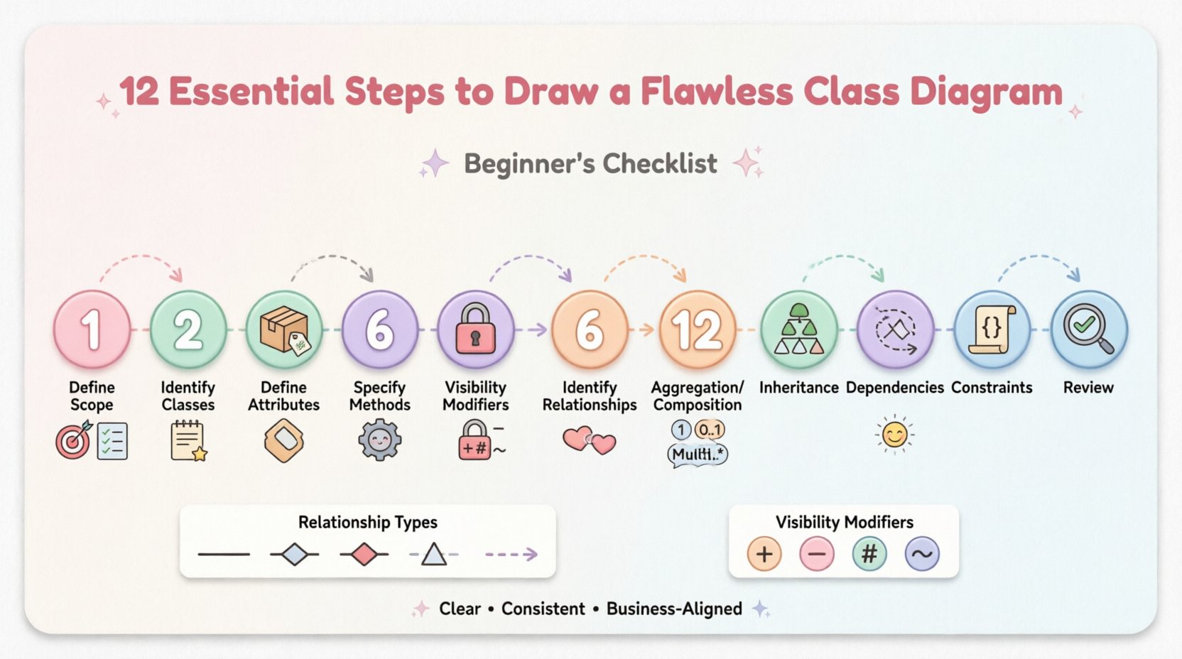
The 12-Step Checklist for Class Diagrams ✅
Below is a detailed breakdown of the essential steps required to construct a reliable model. Each step builds upon the previous one, ensuring a solid foundation for your design.
1. Define the Scope and Objective 🎯
Before drawing a single box, understand the boundaries of the system. What functionality does this diagram cover? Is it for the entire application or a specific module? Defining the scope prevents scope creep, where unrelated classes are added, cluttering the model. Write down the primary goal of this diagram. Are you documenting existing legacy code, or designing a new feature? This context guides every subsequent decision.
2. Identify Key Classes from Requirements 📝
Classes are typically derived from nouns found in the system requirements or user stories. Review the functional specifications and highlight entities that represent real-world objects or concepts. Examples include Customer, Order, or Product. Do not include utility classes or temporary objects yet. Focus on the core domain entities that hold significant state and behavior. This step ensures the diagram remains focused on business value.
3. Define Attributes for Each Class 📦
Attributes represent the state or data held by a class. List the variables that define the object’s current condition. For a Customer class, attributes might include name, email, and address. Avoid overloading a class with too many attributes, as this suggests a violation of separation of concerns. Group related data logically. Ensure that every attribute has a clear purpose tied to the business rules defined in the requirements phase.
4. Specify Methods and Operations ⚙️
Methods define the behavior of the class. These are the actions the object can perform. For a Product class, methods might include calculateDiscount() or updatePrice(). When listing operations, focus on public interfaces that other classes will interact with. Internal helper functions do not always need to be visible on the diagram unless they are critical to understanding the flow. Keep method names descriptive and use standard naming conventions to improve readability.
5. Determine Visibility Modifiers 🔒
Visibility controls access to attributes and methods. This is a critical aspect of encapsulation. There are four standard modifiers:
- Public (+): Accessible from any class.
- Private (-): Accessible only within the class.
- Protected (#): Accessible within the class and its subclasses.
- Package (~): Accessible within the same package or namespace.
Mark each attribute and method with the appropriate symbol. Defaulting to private for data members and public for operations is a common best practice. This distinction enforces data integrity and prevents external code from manipulating internal state directly.
6. Identify Relationships Between Classes 🔗
Classes rarely exist in isolation. They interact through relationships. Identify how one class uses or connects to another. The most fundamental relationship is association. This represents a structural link where objects are connected. For example, a Customer places an Order. This implies a link between the two entities. Draw lines connecting the relevant classes to visualize these connections clearly.
7. Specify Multiplicity and Cardinality 🔢
Multiplicity defines how many instances of one class relate to another. It answers the question: “How many?”. Use notations such as:
- 1: Exactly one instance.
- 0..1: Zero or one instance.
- 1..*: One or many instances.
- 0..*: Zero or many instances.
Place these notations at the ends of association lines. For instance, one Customer can place many Orders, denoted as 1..*. Conversely, an Order belongs to exactly one Customer, denoted as 1. Accurate multiplicity prevents logical errors in the database schema and application logic later.
8. Model Aggregation and Composition 🧩
These are specialized forms of association that describe ownership. Aggregation represents a “has-a” relationship where the part can exist independently of the whole. Think of a Department and Employees. If the department dissolves, employees still exist. Use an empty diamond to indicate this. Composition implies stronger ownership where the part cannot exist without the whole. A House and its Rooms fit this model. If the house is destroyed, the rooms cease to exist. Use a filled diamond for composition. Distinguishing these correctly impacts lifecycle management.
9. Establish Inheritance Hierarchies 🌳
Inheritance allows classes to share common attributes and behaviors. This is the “is-a” relationship. If you have a Vehicle class, you might have subclasses like Car and Truck. Draw a solid line with a hollow triangle pointing to the superclass. This promotes code reuse and reduces redundancy. Ensure that the hierarchy remains logical. Avoid deep hierarchies that make the system hard to navigate. Keep the depth to a reasonable level, typically three to four layers.
10. Model Dependencies 🔄
Dependencies occur when a change in one class affects another, but they are not strongly coupled. This is often a “uses-a” relationship. A ReportGenerator might depend on a DataRepository to fetch information. Use a dashed line with an open arrow to represent this. Dependencies indicate loose coupling. High dependency density can make the system fragile. Minimize these links where possible to maintain modularity.
11. Add Constraints and Business Rules 📜
Not all rules can be enforced by code alone. Some require documentation. Use notes or constraints to specify business logic. For example, an Order cannot be cancelled if the Status is “Shipped”. Use curly braces {} or a specific notation for constraints. This bridges the gap between technical design and business requirements. It ensures that the logic is preserved even if the implementation details change.
12. Review for Consistency and Clarity 🔍
The final step is a comprehensive audit. Check that all classes follow the same naming convention. Ensure that relationships are bidirectional where appropriate, or explicitly marked as unidirectional. Verify that visibility modifiers are consistent across the diagram. Check for orphaned classes that have no relationships. A clean diagram is easier to maintain. If a reader cannot understand the model without a legend, refine the labels. Consistency is key to long-term usability.
Common Relationship Types Explained 🤝
Understanding the nuances of relationships is vital for an accurate diagram. The table below summarizes the standard notations used in modeling.
| Relationship Type | Notation | Description | Example |
|---|---|---|---|
| Association | Solid Line | A structural link between objects. | Teacher teaches Student |
| Aggregation | Empty Diamond | Part can exist independently of the whole. | Library has Books |
| Composition | Filled Diamond | Part cannot exist without the whole. | Company owns Departments |
| Generalization | Solid Line + Hollow Triangle | Inheritance relationship. | Animal is Mammal |
| Dependency | Dashed Line + Open Arrow | One class uses another temporarily. | Class uses Utility Class |
Visibility Modifiers Reference 📋
Consistency in visibility is often overlooked but essential for encapsulation. Refer to this quick guide when drawing your boxes.
| Modifier | Symbol | Access Level |
|---|---|---|
| Public | + | Accessible to all classes |
| Private | – | Accessible only within the class |
| Protected | # | Accessible within class and subclasses |
| Package | ~ | Accessible within the same package |
Finalizing Your Model for Implementation 🚀
Once the checklist is complete, the diagram is ready for review. Present the model to stakeholders to verify that it matches their expectations. Ask questions about edge cases that might not be visible in the static view. Ensure that the design supports scalability. If a new feature requires a significant change to the class structure, revisit the design early rather than refactoring later. A well-documented diagram serves as a reference for future developers, reducing onboarding time and minimizing errors during code implementation.
By adhering to these 12 steps, you create a clear, maintainable, and accurate representation of your system’s architecture. The effort invested in the design phase pays dividends during development and maintenance. Focus on clarity, consistency, and alignment with business needs to produce diagrams that truly serve their purpose.