When starting a new software project, the most critical step often happens before writing a single line of code. This step involves planning the structure of your application using visual models. Among the various diagrams available in the Unified Modeling Language (UML), the Class Diagram stands out as the backbone of object-oriented design. It serves as a blueprint, showing the static structure of the system. Understanding the components of a class diagram is essential for any developer aiming to build scalable and maintainable systems.
This guide provides a detailed look at every element within a class diagram. We will explore how to define classes, manage relationships, and apply visibility rules. By mastering these concepts, you ensure your code reflects a logical architecture that teams can follow easily.
What Is a Class Diagram? 🏗️
A class diagram is a static structure diagram that describes the structure of a system by showing the system’s classes, their attributes, operations (or methods), and the relationships among objects. Unlike sequence diagrams which show behavior over time, class diagrams focus on the static structure.
- Static Structure: It represents the system at a specific point in time.
- Object-Oriented: It aligns with how most modern languages like Java, C++, and Python organize data.
- Documentation: It acts as a contract between developers and stakeholders.
Think of it as an architectural floor plan for a house. You do not need to see the plumbing or electrical wiring to understand the rooms and walls. Similarly, a class diagram shows the “rooms” (classes) and how they connect, without detailing the specific logic inside every function.
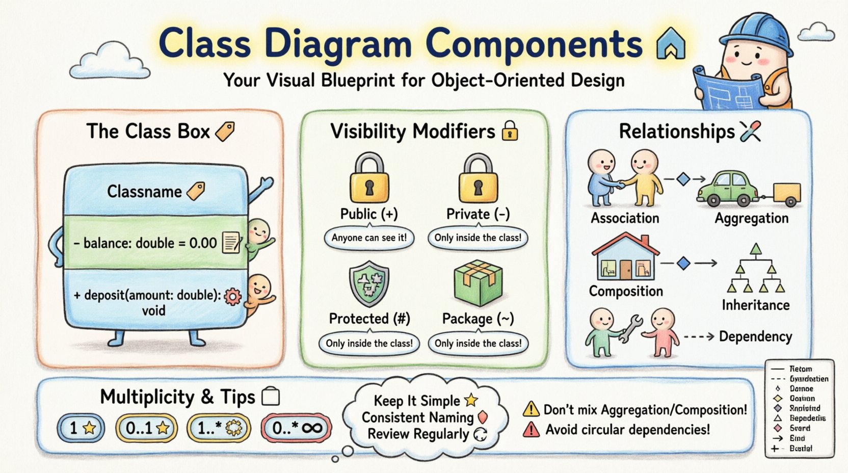
Core Components of a Class Box 📦
At the heart of a class diagram is the Class Box. This rectangle represents a single class in your system. It is typically divided into three compartments.
1. Class Name (Top Compartment) 🏷️
The top section holds the name of the class. Naming conventions are vital here. Use CamelCase for class names (e.g., UserAccount, PaymentProcessor). This distinguishes the class from attributes and methods.
- Capitalization: Always start with an uppercase letter.
- Uniqueness: Ensure the name is unique within the package or namespace.
- Noun-Based: Classes should generally represent nouns (e.g., Customer, Order), not verbs.
2. Attributes (Middle Compartment) 📝
The middle section lists the properties or attributes of the class. Attributes represent the state or data held by an object of this class.
Each attribute typically follows this format:
visibility name : type = initialValue
- Visibility: Defines who can access the attribute (see section on Visibility Modifiers).
- Name: The variable name used in code.
- Type: The data type (e.g., String, Integer, Boolean).
- Initial Value: An optional default value assigned upon creation.
Example: - balance : double = 0.00
3. Operations / Methods (Bottom Compartment) ⚙️
The bottom section lists the operations or methods. These are the behaviors the class can perform.
The format usually looks like this:
visibility operationName (parameters) : returnType
- Operation Name: Verbs describing an action (e.g.,
calculateTotal,login). - Parameters: Input values required to execute the method.
- Return Type: The data type returned after execution.
Example: + deposit(amount : double) : void
Visibility Modifiers 🔒
Visibility determines the accessibility of attributes and methods from other classes. This is a key concept in encapsulation. There are four standard symbols used in diagrams.
- Public (+): Accessible from any class. This is the most open level of access.
- Private (-): Accessible only within the class itself. This is the default in many languages and is the safest for internal data.
- Protected (#): Accessible within the class and its subclasses (children). This supports inheritance.
- Package (~): Accessible only within the same package or namespace. This is often used for internal utility classes.
Using the correct visibility modifier prevents unintended side effects. If you expose a private attribute as public, other parts of your code can modify it directly, bypassing validation logic.
Understanding Relationships 🔗
Classes rarely exist in isolation. They interact with each other to form a complete system. These interactions are depicted using lines connecting the classes, known as relationships. Understanding the difference between these lines is crucial for accurate modeling.
1. Association 🔗
An association represents a structural relationship where objects of one class are linked to objects of another. It is a general term for a link.
- Solid Line: Used to draw a standard association.
- Direction: An arrow indicates the navigability (who knows about whom).
- Example: A
Teacherteaches aStudent.
2. Aggregation 🟢
Aggregation is a special form of association representing a “whole-part” relationship where the parts can exist independently of the whole.
- Hollow Diamond: Placed on the “whole” side of the line.
- Independence: If the whole is destroyed, the parts remain.
- Example: A
DepartmenthasEmployees. If the department is closed, the employees can still exist elsewhere.
3. Composition 🟦
Composition is a stronger form of aggregation. It implies that the parts cannot exist without the whole.
- Solid Diamond: Placed on the “whole” side of the line.
- Dependency: If the whole is destroyed, the parts are destroyed with it.
- Example: A
HousehasRooms. If the house is demolished, the rooms cease to exist as part of that house.
4. Generalization (Inheritance) 📉
Generalization represents an “is-a” relationship. A subclass inherits attributes and operations from a superclass.
- Empty Triangle Arrow: Points from the subclass to the superclass.
- Reusability: Allows code reuse and polymorphism.
- Example: A
Caris aVehicle. ASedanis aCar.
5. Dependency 🔄
Dependency indicates that one class uses or depends on another, but only temporarily. It is often a “uses-a” relationship.
- Dashed Arrow: Points from the dependent class to the used class.
- Temporality: The relationship is usually short-lived (e.g., a method parameter).
- Example: A
ReportGeneratoruses aDatabaseConnectionto fetch data, but does not hold a reference to it permanently.
To clarify these relationships, refer to the comparison table below.
| Relationship Type | Symbol | Meaning | Lifetime of Part |
|---|---|---|---|
| Association | Solid Line | Structural link | Independent |
| Aggregation | Hollow Diamond | Whole-Part (Weak) | Independent |
| Composition | Solid Diamond | Whole-Part (Strong) | Dependent |
| Inheritance | Triangle Arrow | Is-A Relationship | N/A |
| Dependency | Dashed Arrow | Uses-a Relationship | Temporary |
Multiplicity and Cardinality 📐
Multiplicity defines how many instances of one class relate to how many instances of another. This is often written as a range near the ends of the relationship lines.
- 1: Exactly one.
- 0..1: Zero or one (optional).
- 1..*: One or more (mandatory).
- 0..*: Zero or more (optional collection).
- n: A specific number.
Example Scenario: Consider a Library and a Book.
- A Library must have at least one Book (
1..*). - A Book belongs to exactly one Library (
1).
Defining multiplicity correctly prevents logic errors. For instance, if you model a relationship as 0..1 but your code requires at least one, you will encounter null reference errors.
Interfaces and Abstract Classes 🧩
Not all classes are meant to be instantiated. Some serve as templates or contracts.
Abstract Classes
An abstract class cannot be instantiated directly. It provides a base implementation for subclasses. In a diagram, the class name is typically written in italic or marked with the keyword {abstract}.
- Used for shared behavior among a group of classes.
- Can contain both abstract methods (no body) and concrete methods (with body).
Interfaces
An interface defines a set of methods that a class must implement. It does not store state (attributes).
- Used to define a contract across unrelated classes.
- In diagrams, often represented by a class box with the keyword
{interface}or a stereotype icon. - Enables polymorphism where different classes can be treated uniformly.
Understanding the distinction is vital. Use an interface when you need a common behavior across different types. Use an abstract class when you need to share code and state.
Best Practices for Beginners 🎓
Creating class diagrams requires discipline. Here are several guidelines to ensure your diagrams remain useful and accurate.
- Keep It Simple: Do not try to model the entire system in one diagram. Break it down into subsystems or packages.
- Focus on Essential Elements: Do not include every single method. Include the most significant ones that define the class behavior.
- Consistent Naming: Stick to a strict naming convention. If you use
camelCasefor attributes, use it everywhere. - Review Regularly: As the code evolves, the diagram should too. A diagram that is outdated is worse than no diagram.
- Use Tools Wisely: Use diagramming software to maintain consistency, but ensure the logic comes from your mind, not the tool.
Common Mistakes to Avoid 🚫
Even experienced developers make errors when modeling. Being aware of common pitfalls can save you time during refactoring.
- Mixing Aggregation and Composition: These are often confused. Remember: if the part dies with the whole, it is Composition. If the part survives, it is Aggregation.
- Over-Engineering: Do not create deep inheritance hierarchies (Grandfather -> Father -> Son -> Child). This makes the code rigid and hard to change.
- Ignoring Multiplicity: Forgetting to define how many objects are linked can lead to ambiguity in the code implementation.
- Circular Dependencies: Avoid situations where Class A depends on Class B, and Class B depends on Class A. This creates a cycle that complicates initialization.
From Diagram to Code 💻
The final step is translating the visual model into actual source code. This process is often called “forward engineering”.
- Generate Code: Many tools can generate skeleton code from a class diagram.
- Reverse Engineer: You can also generate a diagram from existing code to document legacy systems.
- Manual Mapping: Sometimes, manual mapping is better. You might need to refactor the diagram to fit the language features you are using.
Ensure that the visibility modifiers in your code match the symbols in your diagram. Private attributes in the diagram must be private in the code. This alignment ensures data integrity.
Conclusion: Building a Strong Foundation 🚀
Creating class diagrams is more than just drawing boxes and lines. It is a thinking process that forces you to define the structure of your software before you build it. By understanding the components, relationships, and rules outlined in this guide, you establish a solid foundation for your projects.
Start small. Model a simple class. Add attributes. Add methods. Connect it to another class. Gradually increase complexity. This iterative approach allows you to learn the nuances of object-oriented design without becoming overwhelmed.
Remember, the goal is clarity. A good class diagram communicates intent clearly to other developers. It reduces ambiguity and sets the stage for robust, maintainable code. Take your time, follow the standards, and you will find that your coding process becomes more structured and efficient.