Modeling Real-Time Control Logic with Visual Paradigm’s AI Diagram Generator
🔍 Introduction
Electric vehicles (EVs) are transforming transportation, but their adoption hinges on reliable, intelligent, and safe charging infrastructure. A Level 3 DC Fast Charging Station is a critical component in this ecosystem — capable of delivering high-power energy in minutes rather than hours.
This case study presents a comprehensive UML State Machine Diagram for a Smart EV Charging Station, modeled using Visual Paradigm’s AI Diagram Generator. The goal is to illustrate how UML state diagrams can be used to model complex real-time control logic involving safety interlocks, hardware synchronization, user interaction, and emergency response protocols.
We will break down the system using core UML state diagram concepts, explain each transition and behavior, and demonstrate how modern diagramming tools can generate professional, production-ready visualizations.
🧩 Core Problem Domain: Smart EV Charging Station
Objective
Design a real-time state machine to manage the lifecycle of a DC fast charging session, ensuring:
-
User authentication via RFID
-
Physical safety interlocks (plug detection)
-
Dynamic charging modes (High Power / Trickle Charge)
-
Real-time monitoring (thermal faults)
-
Graceful shutdown and billing
-
Emergency stop override
This is not just a software logic problem — it’s a safety-critical embedded system involving high-voltage transfer, requiring robust state modeling.
📌 Key UML State Diagram Concepts Applied
| Concept | Definition | Application in This Model |
|---|---|---|
Initial Pseudostate ([*]) |
Entry point of the state machine | Start from Available state |
| Composite States | States with sub-states | Charging contains HighPower and TrickleCharge |
| Entry/Exit Actions | Actions executed on entry or exit | entry / UnlockConnector, entry / CutPower |
| Do Activities | Ongoing actions during state | do / TransferPower |
| Transitions | State changes triggered by events | CardSwiped, PlugDetected, ThermalFault |
| Self-Transitions | No state change, same state | Not explicitly used, but implied in monitoring |
| Guard Conditions | Conditional checks before transition | Battery > 80%, BatteryFull, ThermalFault |
| Final State | End of lifecycle | None — system loops back to Available |
| History States | Resume previous sub-state | Not needed here (simple flow) |
| Deep History (H) | Re-enter most recent sub-state | Not applicable, but could be added for advanced recovery |
✅ Visual Paradigm’s AI Diagram Generator automatically infers best practices like:
Proper nesting of states
Semantic use of
entry,exit, anddoactionsCorrect use of event-triggered transitions with guards
Clean layout and alignment
🖼️ Generated UML State Diagram (Visual Paradigm AI Output)
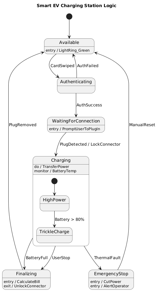
@startuml
title Smart EV Charging Station Logic
[*] --> Available

state Available {
  Available : entry / LightRing_Green
}

Available --> Authenticating : CardSwiped
Authenticating --> Available : AuthFailed
Authenticating --> WaitingForConnection : AuthSuccess

state WaitingForConnection {
  WaitingForConnection : entry / PromptUserToPlugIn
}

WaitingForConnection --> Charging : PlugDetected / LockConnector

state Charging {
  Charging : do / TransferPower
  Charging : monitor / BatteryTemp

  state "HighPower" as HP
  state "TrickleCharge" as TC

  [*] --> HP
  HP --> TC : Battery > 80%
}

Charging --> Finalizing : BatteryFull
Charging --> Finalizing : UserStop
Charging --> EmergencyStop : ThermalFault

state Finalizing {
  Finalizing : entry / CalculateBill
  Finalizing : exit / UnlockConnector
}

Finalizing --> Available : PlugRemoved

state EmergencyStop {
  EmergencyStop : entry / CutPower
  EmergencyStop : entry / AlertOperator
}

EmergencyStop --> Available : ManualReset

@enduml
✅ Visualized Output (via Visual Paradigm AI)
(Note: You can generate this using Visual Paradigm Online → AI Diagram Generator → “Create State Machine from Text”)
🧱 State-by-State Breakdown
1. Available – Standby Mode
-
Purpose: Initial state where the charger is idle and ready.
-
Entry Action:
LightRing_Green— indicates availability. -
Trigger:
CardSwiped→ user taps RFID card.
💡 This state is passive until triggered. It enforces no resource allocation.
2. Authenticating – User Authorization
-
Purpose: Verify user identity via RFID.
-
Transitions:
-
AuthFailed→ return toAvailable -
AuthSuccess→ move toWaitingForConnection
-
-
Key Insight: This is where payment authorization could be integrated (see extensions below).
🛡️ Security Layer: Only authenticated users can access the physical connector.
3. WaitingForConnection – Safety Wait Phase
-
Purpose: Prevents energization until plug is physically secured.
-
Entry Action:
PromptUserToPlugIn— e.g., LED flash, display message. -
Transition:
PlugDetected→ locks connector and entersCharging.
⚠️ Critical Safety Interlock: No power transfer occurs without physical connection.
4. Charging – Dynamic Power Transfer State
-
Composite State with Sub-states:
-
HighPower: Full charging (0–80%) -
TrickleCharge: Slower charge (>80%) to protect battery life
-
-
Do Activity:
TransferPower— continuous power delivery. -
Monitor:
BatteryTemp— real-time thermal monitoring. -
Transitions:
-
Battery > 80%→TrickleCharge -
BatteryFull→Finalizing -
UserStop→Finalizing -
ThermalFault→EmergencyStop(immediate)
-
🔄 Dynamic Behavior: Charging speed adapts based on battery state — mimicking real-world DC fast chargers.
5. EmergencyStop – Critical Safety Override
-
Purpose: Global emergency protocol.
-
Entry Actions:
-
CutPower— immediately de-energize the DC link -
AlertOperator— send alert to central monitoring system
-
-
Transition:
ManualReset→ returns toAvailable
🚨 Non-negotiable Safety Rule: This state can be entered from any other state, ensuring real-time responsiveness.
6. Finalizing – Post-Charge Processing
-
Entry Action:
CalculateBill— compute cost based on kWh used and rate. -
Exit Action:
UnlockConnector— release physical lock. -
Transition:
PlugRemoved→ back toAvailable
💸 Business Logic: Ensures payment is finalized before allowing disconnection.
🔗 Key Transitions & Guard Conditions
| Trigger | Source | Target | Guard Condition | Action |
|---|---|---|---|---|
CardSwiped |
Available |
Authenticating |
— | — |
AuthFailed |
Authenticating |
Available |
— | — |
AuthSuccess |
Authenticating |
WaitingForConnection |
— | — |
PlugDetected |
WaitingForConnection |
Charging |
— | LockConnector |
BatteryFull |
Charging |
Finalizing |
Battery == 100% |
— |
UserStop |
Charging |
Finalizing |
User selects “Stop” | — |
ThermalFault |
Charging |
EmergencyStop |
BatteryTemp > 85°C |
CutPower, AlertOperator |
PlugRemoved |
Finalizing |
Available |
— | — |
ManualReset |
EmergencyStop |
Available |
— | — |
✅ Guard conditions like
Battery > 80%are critical for adaptive behavior and prevent premature state changes.
📈 Why This Model Matters: Real-World Impact
| Benefit | Description |
|---|---|
| Safety First | Emergency stop globally overrideable — prevents fire or explosion |
| Energy Efficiency | Trickle charge reduces stress on battery at high SOC |
| User Experience | Clear feedback via lights, prompts, and feedback loops |
| Scalability | Easy to extend with network failures, payments, or remote monitoring |
| Compliance-ready | Aligns with ISO 15118 (Plug & Charge), IEC 61851 standards |
🔧 Industrial Use Case: This model is directly applicable in smart city infrastructure, utility grid integration, and fleet management systems.
✨ Optional Extensions (Future-Proofing)
While the current model is robust, consider enhancing it with:
-
PaymentFailedState-
Trigger:
PaymentDeclinedafter auth -
Transition:
Authenticating→PaymentFailed→Available -
Prevents charging without payment.
-
-
NetworkOfflineState-
Trigger:
NoNetwork -
Behavior: Allow limited local charging with delayed billing
-
Useful for rural or low-connectivity areas.
-
-
MaintenanceModeState-
Entry:
MaintenanceRequest -
Prevents all operations until serviced
-
-
History States (
H)-
Add deep history to
Chargingto resume fromHighPowerorTrickleChargeafter interruption.
-
💬 Tip: Visual Paradigm’s AI can auto-generate these extensions when prompted:
“Add payment failure handling and network outage states to this charging station model.”
📌 Conclusion: Why UML State Diagrams Win for Embedded Systems
The Smart EV Charging Station case study demonstrates how UML state diagrams are not just academic tools — they are engineering blueprints for safety-critical systems.
Using Visual Paradigm’s AI Diagram Generator, we transformed a complex business logic into:
-
A clear, structured, and maintainable representation
-
A shared language between engineers, developers, and safety auditors
-
A foundation for verification, testing, and regulatory compliance
🏁 Final Thought:
In high-stakes environments like EV charging, where a single misstep can lead to equipment damage, injury, or fire, modeling control logic with UML isn’t optional — it’s essential.
📎 Appendix: How to Generate This Diagram Using Visual Paradigm
-
Click on “AI Diagram Generator“
-
Paste the PlantUML code from above
-
Click “Generate”
-
Export as PNG/SVG or embed in documentation
🔄 Bonus: You can also generate Java or C++ code stubs from the state machine for embedded firmware integration.
📣 Call to Action
✅ Want to extend this model with:
-
Real-time payment integration?
-
IoT telemetry (e.g., remote monitoring)?
-
Fault tolerance & auto-recovery?
👉 Let Visual Paradigm’s AI do the heavy lifting. Ask:
“Generate a next-gen EV charging state machine with network fault tolerance and billing integration.”
Articles and resources:
- Mastering State Diagrams with Visual Paradigm AI: A Guide for Automated Toll Systems: This guide demonstrates how to use AI-enhanced state diagrams to model and automate the complex logic required for toll system software.
- Definitive Guide to UML State Machine Diagrams with AI: This resource provides a detailed look at using AI-powered tools to accurately model object behavior with UML state machine diagrams.
- Interactive State Machine Diagram Tool: A specialized web-based tool for creating and editing state machine diagrams that leverages GenAI capabilities for real-time behavior modeling.
- Generating Source Code from State Machines in Visual Paradigm: This technical guide provides instructions on generating implementation code directly from state machine diagrams to execute state-driven logic.
- Visual Paradigm – UML State Machine Diagram Tool: An overview of a cloud-based interface designed for architects to build, edit, and export precision state machine models.
- 3D Printer State Machine: A Comprehensive Step-by-Step Guide: A walkthrough of the state machine concept as applied to 3D printing systems, explaining their operational logic and automation paths.
- State Diagram Quick Tutorial: Master UML State Machines in Minutes: A beginner-friendly tutorial for mastering UML state machines, covering core concepts and modeling techniques within Visual Paradigm.
- Visualizing System Behavior: A Practical Guide to State Diagrams with Examples: An analysis of how state diagrams provide an intuitive visualization to identify potential system issues early in the design process.
- Creating State Machine Diagrams in Visual Paradigm: Official documentation detailing how to design and implement system behavior modeling using state machine diagrams.
- Visual Paradigm AI Suite: A Comprehensive Guide to Intelligent Modeling Tools: This overview details how the platform’s AI Chatbot supports technical modeling, including state machines and other behavioral diagrams, within the modeling environment.