In the landscape of software architecture and data modeling, few concepts carry as much weight as the relationships between entities. When designing a system, understanding how objects interact is just as critical as defining the objects themselves. This interaction is formally expressed through class diagram multiplicity, a notation that dictates the quantitative association between two classes. Whether you are mapping out a database schema or structuring an object-oriented codebase, clarity here prevents architectural debt before it begins.
Multiplicity defines the constraints on the number of instances of one class that can be associated with instances of another class. It answers fundamental questions: Can one user own multiple profiles? Can a single order belong to multiple customers? These distinctions shape the flow of data and the integrity of the application. This guide explores the core cardinalities—1:1, 1:N, and N:N—providing a detailed look at their implementation, implications, and common pitfalls.
Understanding the Foundation: Notation and Terminology 🧩
Before diving into specific relationship types, it is essential to establish the vocabulary used in Unified Modeling Language (UML) and general data modeling. Multiplicity is not merely about counting; it is about defining rules.
- Cardinality: The number of instances of a class that can participate in a relationship. This is often expressed using numbers like
1,*, or ranges like0..1. - Optionality: Whether an instance of a class is required to participate in the relationship. For example, does every employee need a manager?
- Association: The link itself, representing a structural relationship between classes.
When you look at a class diagram, you will see lines connecting boxes. Near these lines, small numbers or symbols indicate the multiplicity. These symbols act as contracts. If the system logic violates these contracts, the data becomes inconsistent. Understanding this notation is the first step toward robust design.
The One-to-One Relationship (1:1) 🔗
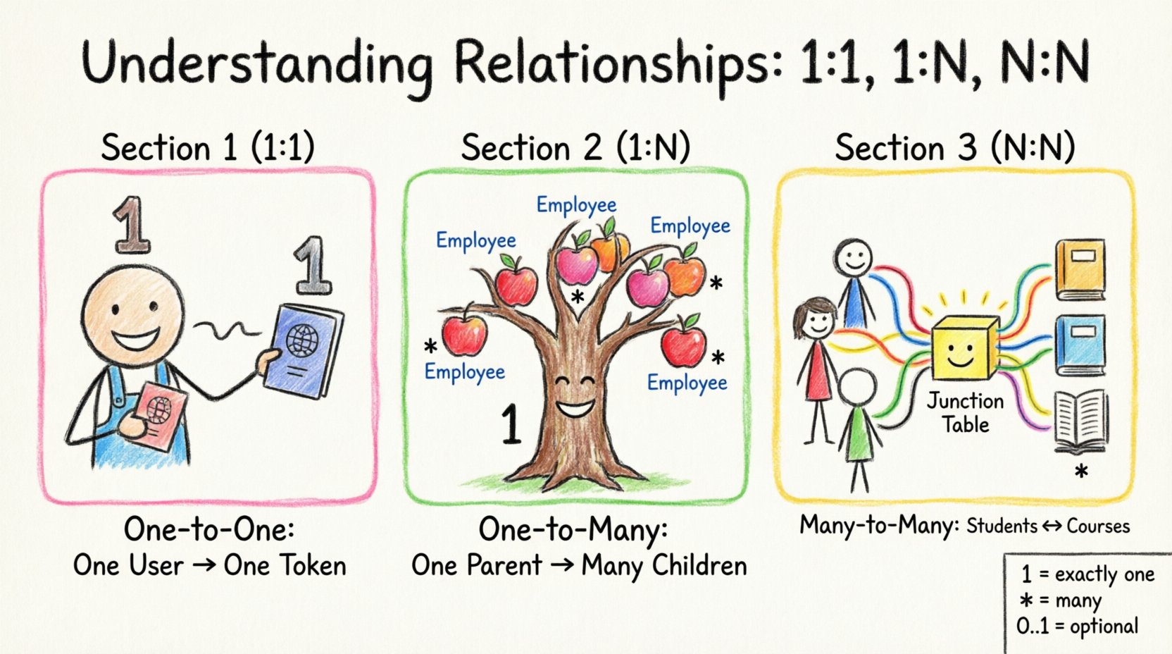
The one-to-one relationship is the most restrictive of the standard associations. It implies that for every instance of Class A, there is at most one instance of Class B, and vice versa. This is often represented by the notation 1 on both ends of the association line.
When to Use 1:1 Associations
This relationship type is suitable when two concepts are essentially different views of the same entity, or when the association is exclusive and permanent.
- Authentication Tokens: A User account may have exactly one active session token at a time. If a user logs in again, the previous token is invalidated.
- Identity Documents: A Passport is issued to one specific Citizen, and a Citizen holds one primary Passport at a time.
- Configuration Settings: A specific Application instance often has a single Configuration object holding its runtime parameters.
Implementation Considerations
Implementing a 1:1 relationship requires careful attention to foreign keys and database constraints. In a relational database context, this is typically achieved by placing a foreign key in one of the tables that references the primary key of the other.
- Database Foreign Keys: You must add a
FOREIGN KEYconstraint to ensure referential integrity. This prevents orphaned records. - Unique Constraints: To enforce the “one” side strictly, the column containing the foreign key must have a
UNIQUEconstraint. This ensures no two rows can point to the same parent. - Code References: In object-oriented code, this usually manifests as a direct reference to a single object rather than a collection. A
Userclass might have a propertyProfileof typeProfile, notList<Profile>.
The One-to-Many Relationship (1:N) 🌳
The one-to-many relationship is the most common association in enterprise systems. Here, a single instance of Class A is associated with zero or more instances of Class B. However, each instance of Class B is associated with exactly one instance of Class A. The notation typically shows 1 on one end and * (or 0..*) on the other.
Common Scenarios
This pattern describes hierarchical data where a parent owns multiple children.
- Orders and Line Items: A single Order contains many Line Items, but each Line Item belongs to only one Order.
- Departments and Employees: A Department employs many Employees, but an Employee is assigned to only one Department (in a simple structure).
- Categories and Products: A Product Category includes many Products, but a Product belongs to one specific Category.
Structuring the Data
Implementing 1:N relationships is straightforward in relational databases but requires specific handling in memory models.
- Foreign Key Placement: The foreign key resides in the “many” side (the child table). The Order table will have an
order_idcolumn linking to the Line Items table. - Collection Management: In the “one” side (the parent object), you typically maintain a collection. A
Customerobject will contain a list or array ofOrderobjects. - Performance Implications: Retrieving the “many” side can become expensive if the collection is large. Lazy loading is often employed to fetch child objects only when accessed, reducing initial query overhead.
Handling Cascading Deletes
A critical decision in 1:N design is what happens when the parent is removed. If you delete a Department, do you delete all Employees? Usually, the answer is no, but the system must handle it.
- Cascade Delete: Automatically removes all child records when the parent is deleted. Useful for temporary data like Order Logs.
- Restrict Delete: Prevents deletion of the parent if children exist. Useful for core data like Products.
- Nullify: Sets the foreign key in the child to null. Requires the child to allow null values.
The Many-to-Many Relationship (N:N) 🕸️
The many-to-many relationship is the most complex of the three. It occurs when instances of Class A can be associated with multiple instances of Class B, and instances of Class B can be associated with multiple instances of Class A. The notation shows * (or 0..*) on both ends.
Real-World Examples
This relationship is common in scenarios involving tags, roles, or enrollment.
- Students and Courses: A Student enrolls in many Courses, and a Course has many Students.
- Authors and Books: An Author writes many Books, and a Book can have multiple Authors (co-authors).
- Skills and Employees: An Employee has many Skills, and a Skill is possessed by many Employees.
The Junction Entity Solution
Directly implementing N:N relationships in a relational database is not possible. A single foreign key cannot link two tables bidirectionally without ambiguity. The solution is the introduction of a junction table (or associative entity).
This intermediate table breaks the N:N relationship into two 1:N relationships.
- Structure: The junction table contains the primary keys of both related tables as foreign keys.
- Additional Data: Unlike a simple link, a junction table can hold its own attributes. For example, the link between Student and Course might need a
gradeorenrollment_date. - Composite Keys: The primary key of the junction table is often a composite key consisting of the two foreign keys, ensuring a unique pairing.
Object-Oriented Implementation
In code, managing N:N relationships requires maintaining bidirectional consistency. If you add a Course to a Student, you must also add the Student to the Course.
- Synchronization: Helper methods should be created to manage these links. A
Student.addCourse(Course c)method should automatically add the student to the course’s list. - Memory Usage: Because data is duplicated in two collections (Student’s list and Course’s list), memory usage increases. Ensure garbage collection handles orphaned references if a link is removed.
Cardinality vs. Optionality: A Critical Distinction ⚖️
While discussing multiplicity, it is vital to distinguish between how many and whether it is required. These are often conflated but represent different rules.
- Minimum Cardinality: The minimum number of instances required. This is usually 0 or 1.
- Maximum Cardinality: The maximum number of instances allowed. This is usually 1 or many (*).
- Zero or One (0..1): The relationship is optional. The instance may or may not exist.
- One or More (1..*): The relationship is mandatory. The instance must exist and can have multiple.
Consider a Employee and Manager relationship. An Employee must have a Manager (1..1), but a Manager might not manage anyone at a specific moment (0..*). Understanding these nuances allows for precise database constraints and validation logic.
Translating Design to Implementation 🛠️
Once the class diagram is finalized, the transition to actual code and storage requires specific strategies for each relationship type.
Database Schema Design
The physical schema is the most rigid part of the system. Changes here are costly.
- Normalization: Ensure your design follows normalization rules (typically up to 3NF). Redundant data often stems from misunderstanding relationships.
- Indexing: Foreign key columns should be indexed. This speeds up joins and constraint checks significantly.
- Data Types: Ensure the data types of the primary keys match the foreign keys exactly. Mismatched types lead to runtime errors.
Application Layer Logic
The code layer is where business rules enforce the relationship.
- Validation: Before saving an object, validate that the relationship constraints are met. For example, do not allow a Student to enroll in a Course that is already full.
- Transaction Management: When creating or updating related objects, wrap the operations in transactions. This ensures that if one part of the relationship fails, the entire change is rolled back.
- API Responses: When exposing data via an API, decide how deeply to nest related objects. Returning a full Customer object with all their Orders in a single response can lead to performance bottlenecks.
Common Pitfalls and Anti-Patterns 🚫
Even experienced designers make mistakes when defining multiplicity. Recognizing these patterns early saves significant refactoring time later.
- Assuming N:N is Always Necessary: If two entities seem linked, check if they actually need a direct link. Often, a 1:N is sufficient if the relationship is directional.
- Ignoring Optionality: Designing a mandatory link (1..1) when the relationship is actually optional (0..1) leads to data entry errors and rigid systems.
- Circular Dependencies: When Class A references Class B, and Class B references Class A, serialization and memory management can become problematic. Be cautious with deep recursion in traversal algorithms.
- Over-Engineered Junction Tables: Do not create a junction table if the relationship is simple and does not require its own attributes. Sometimes, a single foreign key is enough.
Comparison of Relationship Types 📊
To summarize the differences and trade-offs, refer to this overview of the three primary cardinalities.
| Feature | One-to-One (1:1) | One-to-Many (1:N) | Many-to-Many (N:N) |
|---|---|---|---|
| Notation | 1 — 1 | 1 — * | * — * |
| Database Implementation | Foreign Key with Unique Constraint | Foreign Key in Child Table | Junction Table (Associative Entity) |
| Code Structure | Single Object Reference | Collection/List of Objects | Collection of Collections |
| Query Complexity | Low | Moderate | High (Requires Joins) |
| Flexibility | Low (Strict) | High | Very High |
Final Considerations for Data Integrity ✅
The stability of a software system relies heavily on the correctness of its relationships. When defining multiplicity, you are setting the rules of engagement for your data. A well-defined class diagram acts as a blueprint that aligns the database, the code, and the business logic.
Always test your assumptions. Draw the diagram, implement a prototype, and check if the data flows naturally. If you find yourself constantly adding workarounds to fit data into a 1:N structure that feels like N:N, it is time to revisit the design.
By adhering to these principles, you ensure that your system remains scalable, maintainable, and logically consistent. The effort invested in correctly identifying 1:1, 1:N, and N:N relationships pays dividends in reduced bugs and clearer code structure over the lifecycle of the project.
Key Takeaways
- Notation Matters: Use standard symbols (1, 0..1, *) to communicate intent clearly.
- Database Alignment: Ensure your schema supports the diagram without forcing awkward workarounds.
- Optionality is Key: Distinguish between “must exist” and “may exist” to avoid rigid constraints.
- Manage Complexity: Use junction tables for N:N relationships to maintain referential integrity.
- Validate Early: Check relationships during the design phase to prevent architectural debt.