In the complex landscape of software engineering and information systems, clarity is currency. When developers, architects, and stakeholders collaborate on building robust applications, they require a shared language. The class diagram serves as this universal grammar. It is not merely a drawing; it is a structural blueprint that defines the static architecture of a system. Understanding this tool is fundamental for anyone involved in the design, analysis, or maintenance of object-oriented information systems.
This guide explores the anatomy, purpose, and strategic importance of class diagrams. We will dissect their components, examine the relationships that bind them, and discuss how they influence the lifecycle of information systems. Whether you are a student learning the foundations or a professional refining your architectural skills, this overview provides the necessary depth to grasp the role of these diagrams in modern development.
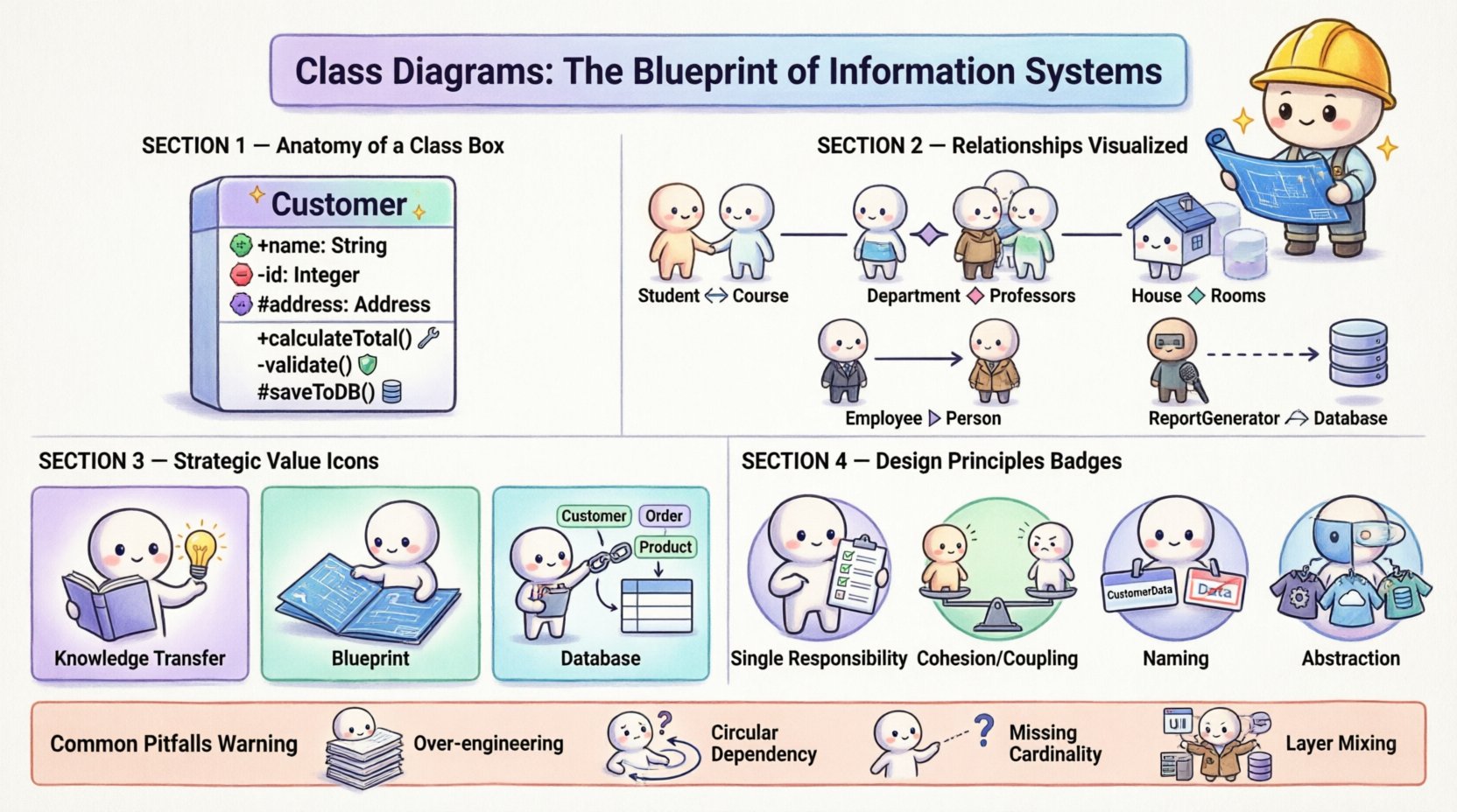
🏗️ Anatomy of a Class Diagram
A class diagram is a type of static structure diagram in the Unified Modeling Language (UML). It describes the structure of a system by showing the system’s classes, their attributes, operations (methods), and the relationships among objects. Unlike sequence diagrams which focus on behavior over time, class diagrams focus on the structure at a specific point in time.
Each element within a class diagram represents a specific aspect of the data model or the logic layer. To understand the diagram, one must understand the boxes that make up the visual representation.
📦 The Class Box
The fundamental building block is the class box. Visually, it is a rectangle divided into compartments. While tools may vary, the standard convention typically includes three sections:
- Class Name: Located in the top compartment. This is the identifier for the class, typically written in bold and capitalized (e.g.,
CustomerorOrder). - Attributes: Located in the middle compartment. These represent the data or state that the class holds. Each attribute should include a visibility modifier (+ for public, – for private, # for protected), the name, and the data type (e.g.,
- name: String). - Operations: Located in the bottom compartment. These represent the behaviors or functions the class can perform. Like attributes, they include visibility, name, and parameters (e.g.,
+ calculateTotal(): float).
🔍 Visibility Modifiers
Encapsulation is a core principle of object-oriented design. Visibility modifiers control access to the internal state of a class. Understanding these symbols is crucial for reading a class diagram:
- Public (+): Accessible from any other class.
- Private (-): Accessible only within the class itself. This ensures data integrity.
- Protected (#): Accessible within the class and its subclasses.
- Package (~/default): Accessible only within the same package or namespace.
🔗 Understanding Relationships and Connections
Classes rarely exist in isolation. They interact with one another to form a cohesive system. The lines connecting the boxes represent these relationships. Misinterpreting these lines can lead to significant architectural flaws. Below, we detail the most common types of relationships.
📊 Comparison of Common Relationships
| Relationship Type | Symbol | Meaning | Example |
|---|---|---|---|
| Association | Solid Line | Structural link between instances | A Student enrolls in a Course |
| Aggregation | Open Diamond | Whole-part relationship (weak) | A Department has Professors |
| Composition | Filled Diamond | Whole-part relationship (strong) | A House contains Rooms |
| Inheritance (Generalization) | Empty Triangle Arrow | Is-a relationship | Employee extends Person |
| Dependency | Dashed Arrow | Usage relationship | ReportGenerator uses Database |
🧩 Association vs. Aggregation vs. Composition
These three concepts are often confused, yet they define different lifecycle dependencies.
- Association: A generic link. Both sides can exist independently. For example, a
Driverand aCarhave an association. If the car is destroyed, the driver still exists. - Aggregation: A specific form of association representing a “has-a” relationship. The parts can exist independently of the whole. A
TeamhasPlayers. If the team dissolves, the players remain. - Composition: A stronger form of aggregation. The part cannot exist without the whole. If the whole is destroyed, the parts are destroyed. A
OrdercontainsOrderItems. If the order is deleted, the specific items for that order are no longer valid.
🏛️ The Strategic Value in System Architecture
Why do we invest time in creating these diagrams? In information systems, the cost of change increases exponentially as the project progresses. Catching structural errors early is vital. Class diagrams serve as a communication bridge between technical and non-technical stakeholders.
📝 Documentation and Knowledge Transfer
Code can be dense and difficult for non-programmers to read. A class diagram abstracts this complexity into visual symbols. It acts as documentation that survives code refactoring. When a new developer joins a team, reviewing the diagrams provides immediate context on how the system is organized. This reduces the onboarding time significantly.
🔨 Blueprint for Implementation
Many development environments support reverse engineering and forward engineering. Forward engineering allows developers to generate code skeletons directly from the class diagram. This ensures that the implementation matches the design intent. Conversely, reverse engineering creates diagrams from existing code, helping to visualize legacy systems where documentation is missing.
🗄️ Database Schema Design
There is a direct correlation between class diagrams and relational database schemas. Classes often map to tables, attributes to columns, and relationships to foreign keys. While Object-Relational Mapping (ORM) handles some of this translation, understanding the class structure helps in designing efficient database indexes and constraints. It clarifies data integrity rules before the database is ever built.
🎯 Principles of Effective Design
Creating a class diagram is an art that requires discipline. A cluttered diagram is worse than no diagram at all. Adhering to design principles ensures the model remains useful as the system evolves.
🔑 Single Responsibility
Each class should have one reason to change. If a class handles both user authentication and email sending, it violates this principle. This makes the system easier to test and modify. In a diagram, this results in more focused classes with smaller, specific responsibilities.
🔗 Coupling and Cohesion
Cohesion refers to how closely related the responsibilities of a class are. High cohesion is desirable; the class should do one thing well. Coupling refers to the dependency between classes. Low coupling is desirable. If Class A depends heavily on Class B, changes in B break A. The goal is to minimize dependencies while maintaining functionality.
📏 Naming Conventions
Consistency is key. Use nouns for classes and verbs for methods. Use camelCase or PascalCase consistently throughout the diagram. Ambiguous names like Data or Manager should be avoided in favor of specific names like CustomerData or InventoryManager.
🔄 Abstraction
Not every attribute needs to be visible in every context. Use interfaces or abstract classes to define contracts without revealing implementation details. This allows the system to be flexible. For example, a PaymentProcessor interface might be implemented by CreditCardProcessor and PayPalProcessor. The rest of the system interacts with the interface, not the specific implementation.
⚠️ Common Errors to Avoid
Even experienced architects make mistakes. Being aware of common pitfalls can save hours of debugging and refactoring later.
- Over-Engineering: Creating diagrams for systems that are too small. Simple scripts may not need complex class hierarchies. Know when a diagram adds value and when it adds overhead.
- Infinite Recursion: Circular dependencies where Class A depends on Class B, which depends on Class A. This can cause compilation errors and logical loops.
- Ignoring Cardinality: Forgetting to label relationships with multiplicity (e.g., 1-to-1, 1-to-many). Without these labels, the logic of the relationship is ambiguous.
- Mixing Layers: Combining UI classes, business logic classes, and database classes in a single diagram. It is better to separate concerns into different packages or sub-diagrams to maintain clarity.
- Static vs. Dynamic Confusion: Remember that class diagrams do not show flow. They do not show the order in which methods are called. Do not try to force dynamic behavior into a static model.
🔄 Integrating Diagrams into the Development Lifecycle
The creation of class diagrams should not be a one-time event at the start of a project. It is an iterative process that evolves with the software.
🚀 Early Design Phase
During requirements gathering, high-level diagrams help identify the main entities. These are often called domain models. They focus on the business concepts rather than technical implementation details.
🛠️ Implementation Phase
As developers write code, the diagram should be updated. If a new relationship is discovered, it must be added. If a class is split, the diagram must reflect that. Keeping the diagram in sync with the code is essential for it to remain a trusted resource.
🔍 Maintenance Phase
When fixing bugs or adding features, the diagram serves as a map. Developers can trace dependencies to understand the impact of a change. Without an updated diagram, this process becomes a guessing game, increasing the risk of introducing new errors.
🌟 Conclusion
The class diagram is a cornerstone of information systems engineering. It provides the structure necessary to manage complexity. By clearly defining classes, attributes, and relationships, teams can build systems that are scalable, maintainable, and understandable. While tools and methodologies evolve, the fundamental need for structural clarity remains constant. Investing time in designing accurate diagrams pays dividends in reduced technical debt and smoother project delivery.
Whether you are designing a small application or a large enterprise system, the principles of class modeling apply. Focus on clarity, maintain low coupling, and ensure your diagrams tell the story of your system accurately. This disciplined approach leads to robust software that stands the test of time.