In the evolving landscape of software engineering, the ability to visualize system architecture is paramount. Unified Modeling Language(UML) class diagrams remain the definitive standard for object-oriented design, acting as the blueprint for complex software systems. However, the traditional methods of manually drawing these diagrams are being rapidly transformed by Artificial Intelligence.
This comprehensive guide explores the core concepts of UML class diagrams, distinguishes them from object diagrams, and deep-dives into how Visual Paradigm is revolutionizing the field with AI-powered modeling, textual analysis, and advanced round-trip engineering capabilities.
Understanding UML Class Diagrams: The Core Concepts
At its heart, a UML class diagramcaptures the static structure of a system. Unlike dynamic diagrams that illustrate behavior over time (such as sequence or activity diagrams), class diagrams provide a structural map. They define the types of objects in the system and the various static relationships that exist between them.
To build an effective model, one must understand the fundamental building blocks:
1. Classes
A class represents a blueprint for objects. It encapsulates the data and behavior relevant to a specific entity within the system. In UML, a class is typically depicted as a rectangle divided into three compartments:
- Class Name: The identifier of the class (e.g., Customer, Order).
- Attributes: The data properties or state held by the class.
- Operations/Methods: The behavioral functions or services the class provides.
2. Visibility Indicators
Defining access control is crucial for encapsulation. UML uses specific symbols to denote visibility:
| Symbol | Visibility Type | Description |
|---|---|---|
| + | Public | Accessible from any other class. |
| – | Private | Accessible only within the class itself. |
| # | Protected | Accessible within the class and its subclasses. |
| ~ | Package/Default | Accessible only by classes within the same package. |
3. Relationships
Classes rarely exist in isolation. The power of a class diagram lies in the relationships, which define how classes interact. Visual Paradigm supports precise modeling of these connections:
- Association: A general relationship where classes are connected (e.g., a Teacher teaches a Student).
- Aggregation: A “has-a” relationship representing a whole/part hierarchy where the part can exist independently of the whole (e.g., a Library has Books, but Books can exist without that specific Library).
- Composition: A strong “part-of” relationship where the child object’s lifecycle is dependent on the parent (e.g., a House and its Rooms).
- Inheritance (Generalization): An “is-a” relationship indicating that a subclass inherits structure and behavior from a superclass.
- Dependency: A relationship where a change in one class (the supplier) may affect another class (the client).
Class Diagrams vs. Object Diagrams: Key Distinctions
While often discussed together, class diagrams and object diagrams serve distinct purposes in the modeling lifecycle. Understanding the difference is vital for accurate system representation.
| Feature | Class Diagram | Object Diagram |
|---|---|---|
| Abstraction Level | High-level Template | Concrete Instance |
| Scope | Abstract rules, definitions, and structure. | Snapshot of runtime instances at a specific moment. |
| Purpose | Domain modeling and software architecture design. | Validating specific scenarios or debugging logical states. |
| Time Dimension | Static (Time-independent). | Snapshot (Specific point in time). |
Visual Paradigm enables users to model both, ensuring that the abstract rules defined in class diagramscan be tested against concrete object scenarios to validate logic before a single line of code is written.
The AI Revolution: Modeling in Visual Paradigm
Manual diagramming can be time-consuming and prone to human error. Visual Paradigm has integrated advanced Artificial Intelligence to shift the focus from “drawing” to “modeling.” By leveraging current AI capabilities, the platform accelerates the creation process, often reducing hours of work to seconds or minutes.
AI-Powered Textual Analysis
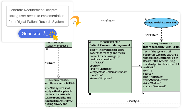
One of the most challenging phases of software development is translating unstructured requirements into a structured design. Visual Paradigm’s AI-Powered Textual Analysis tool addresses this directly.
Users can input natural language text—such as a problem statement, a user story, or a requirements document. The AI engine analyzes this text to automatically extract:
- Candidate Classes
- Attributes and Types
- Operations/Methods
- Relationships between entities
Following extraction, the tool guides the user through a refinement process to ensure UML2.5 compliance. This generates a complete, editable class diagram directly from the requirements text, bridging the gap between business analysts and system architects.
Conversational AI (Chatbot Integration)
For an interactive modeling experience, Visual Paradigm offers an AI Chatbot(accessible via chat.visual-paradigm.com or embedded). This feature allows developers to build diagrams through conversation.
For example, a user might prompt: “Generate a UML class diagram for an online library system including Book, Member, Loan, and relationships.”
The AI instantly interprets the context and produces a professional-grade diagram with:
- Clean, auto-arranged layouts.
- Correct standard notations.
- Context-aware suggestions for improvements.
This iterative process allows users to refine the model naturally (e.g., “Add an attribute for ISBN to the Book class”), making it highly effective for rapid prototyping.
AI-Assisted Class Diagram Generator
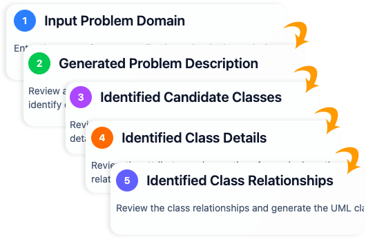
For comprehensive project setups, theAI-Assisted Wizard offers a structured, 10-step guided process. This tool combines simple user inputs with deep AI analysis to:
- Define the scope of the system.
- Fill in structural gaps.
- Propose logical relationships based on domain knowledge.
- Validate structural integrity.
- Generate design analysis reports.
This tool is particularly powerful for exporting models to various formats, including PlantUML, SVG, and JSON, ensuring interoperability with other tools in the development stack.
Bridging Design and Code: Advanced Engineering Capabilities
A diagram is only as useful as its implementation. Visual Paradigm excels in bridging the divide between theoretical design and executable code, supporting full lifecycle development.
1. Source Code Generation
Once a class diagram is finalized, Visual Paradigm can automatically generate production-ready source code. It supports major programming languages such as Java, C#, andC++. This ensures that the class structures, inheritance hierarchies, and method signatures in the code match the design exactly, saving developers from writing boilerplate code manually.
2. ORM Integration
For applications requiring database persistence, the platform facilitates Object-Relational Mapping (ORM). It can produce Hibernate or JPA-compliant persistence code, effectively mapping the object-oriented model to relational database schemas. This automation significantly reduces the complexity of the data access layer.
3. Round-Trip Engineering
Perhaps the most critical feature for maintaining long-term projects is Round-Trip Engineering. Software evolves, and often code changes happen faster than documentation updates.
Visual Paradigm solves this via bidirectional synchronization:
- Forward Engineering: Edit the diagram to update the source code.
- Reverse Engineering: Make changes in the source code and sync them back to the model.
This ensures that the documentation (the model) never becomes stale, providing a single source of truth throughout the application’s lifecycle.
Conclusion
Visual Paradigmdistinguishes itself as an all-in-one platformthat harmonizes traditional UML strengths with cutting-edge AI automation. Whether you are defining a domain model, validating a runtime scenario with object diagrams, or generating Hibernate code for a complex enterprise system, the integration of AI tools—from Textual Analysis to the Conversational Chatbot—ensures that modeling is faster, smarter, and standards-compliant.
For developers, architects, and teams aiming to reduce design time while maintaining high-quality engineering outputs, leveraging these AI-driven capabilities is no longer a luxury, but a competitive necessity.
-
AI-Assisted UML Class Diagram Generator – Visual Paradigm: This tool allows users to generate UML class diagrams with AI-powered suggestions, validation, PlantUML export, and design analysis.
-
AI-Powered UML Class Diagram Generator by Visual Paradigm: Users can generate accurate UML class diagrams from natural language descriptions using AI-assisted automation.
-
Interactive AI Chat for UML Class Diagram Generation: This conversational AI interface enables the generation of UML class diagrams through natural language interaction directly in a web browser.
-
AI-Assisted UML Class Diagram Generator – Visual Paradigm AI Toolbox: This AI-powered tool generates UML class diagrams from text descriptions while requiring minimal manual input.
-
From Problem Description to Class Diagram: AI-Powered Textual Analysis: Visual Paradigm’s AI-powered textual analysis converts natural language problem descriptions into accurate class diagrams.
-
Identifying Domain Classes Using AI Textual Analysis in Visual Paradigm: AI tools in Visual Paradigm automatically identify domain classes from unstructured text to streamline the software modeling process.
-
How AI Enhances Class Diagram Creation in Visual Paradigm: Artificial intelligence automates the design and improves the accuracy of class diagram creation with minimal user input.
-
Streamlining Class Diagrams with Visual Paradigm’s AI: AI tools within the platform reduce the time and complexity required to create accurate class diagrams for software projects.
-
Real-Life Case Study: Generating UML Class Diagrams with Visual Paradigm AI: This case study demonstrates how the AI assistant successfully converts textual requirements into precise UML class diagrams for real-world projects.