Designing software begins before a single line of code is written. It starts with understanding the problem space and organizing information into logical structures. A class diagram serves as the blueprint for object-oriented systems, mapping out the static structure of the software. In this guide, we walk through a practical scenario: modeling a library management system. We will focus on clarity, accuracy, and maintainability.
🧱 Understanding the Foundations of Class Diagrams
A class diagram is a type of Unified Modeling Language (UML) diagram. It describes the structure of a system by showing its classes, attributes, operations, and the relationships among objects. This visual representation allows developers and stakeholders to communicate complex data requirements without ambiguity.
When constructing these diagrams, several core elements must be defined:
- Classes: The building blocks that represent real-world entities or abstract concepts.
- Attributes: The data stored within a class, such as names, IDs, or dates.
- Operations: The behaviors or methods a class can perform, like borrowing an item or returning it.
- Relationships: The links between classes, indicating how they interact.
For a library system, precision is critical. A book is not the same as a loan, and a member is not a librarian. Distinguishing these entities prevents logic errors during implementation.
📋 Defining the Scenario: Library System Requirements
Before drawing lines between boxes, we must understand the business rules. A library system manages physical or digital items, people who access them, and the transactions that occur. Consider the following functional requirements:
- Members can borrow multiple books at once.
- A book can be borrowed by only one member at a time.
- Librarians manage the inventory and assist members.
- Books have categories, authors, and unique identifiers.
- Loans have due dates and status indicators.
These rules dictate the structure of our diagram. We will now break down the modeling process step-by-step.
🔍 Step 1: Identifying Candidate Classes
The first step in modeling is noun analysis. We scan the requirements for nouns that represent significant concepts. Not every noun becomes a class, but they form the initial pool of candidates.
From the requirements above, we extract the following potential classes:
- Book: Represents the physical or digital item available for lending.
- Member: Represents the patron who borrows items.
- Librarian: Represents the staff managing the system.
- Loan: Represents the transaction between a member and a book.
- Category: Represents the genre or section of the library.
Some nouns are too generic or represent data rather than objects. For instance, “title” or “date” are attributes, not classes. We filter these out to keep the model clean.
📝 Step 2: Defining Attributes and Operations
Once classes are identified, we define their internal state and capabilities. Each class needs specific data to function and specific actions it can perform.
Let us examine the Book class in detail:
- Attributes:
- bookId (String): Unique identifier.
- title (String): Name of the work.
- author (String): Creator of the work.
- isbn (String): International Standard Book Number.
- status (Enum): Available, Borrowed, Lost.
- Operations:
- getAvailability(): Boolean
- updateStatus(): Void
Visibility modifiers are also important. Private attributes (marked with -) are internal to the class. Public attributes (marked with +) are accessible from outside. In a library system, the status of a book might be public for the UI to display, while internal processing data remains private.
🔗 Step 3: Establishing Relationships
Classes do not exist in isolation. They interact through relationships. Understanding the type of relationship is vital for accurate modeling.
We primarily use associations to link classes. An association represents a structural link where one class knows about another.
Association Example: Member and Book
A Member borrows a Book. This is a direct association. However, we must define the cardinality. How many books can a member borrow? How many members can borrow a specific book?
We can represent this in a table to ensure clarity:
| Class A | Relationship | Class B | Cardinality | Interpretation |
|---|---|---|---|---|
| Member | Borrows | Book | 1 to 0..* | One member can borrow zero or many books. |
| Book | Is Borrowed By | Member | 0..1 to 1 | A book is borrowed by at most one member at a time. |
Notice the 0..* notation. This means zero or more. The 0..1 means zero or one. This distinction prevents logical errors where two people might borrow the same book simultaneously.
The Loan Class: Resolving Many-to-Many
If a Member can borrow many Books, and a Book can be borrowed by many Members (over time), this creates a many-to-many relationship. In object-oriented design, a many-to-many relationship often requires an intermediate class to hold the attributes of the relationship itself.
In this case, the Loan class acts as this bridge. It holds the date of borrowing, the due date, and the return date. This converts the relationship into two one-to-many relationships:
- Member 1 to Many Loan
- Book 1 to Many Loan
This structure allows us to store specific details about each transaction without cluttering the Member or Book classes.
🌳 Step 4: Handling Inheritance and Generalization
Not all classes are distinct. Some share common characteristics. Inheritance allows us to reduce redundancy by creating a hierarchy.
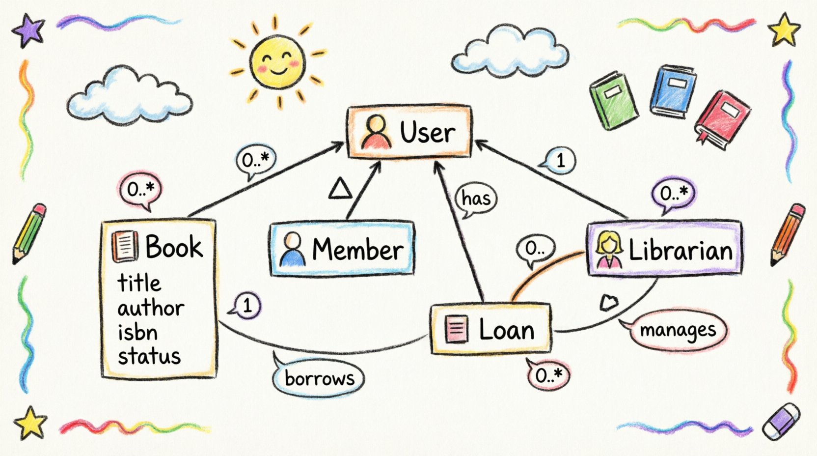
Consider the people who interact with the library. Both Members and Librarians are users of the system. They share common attributes like name, contactInfo, and password. However, Librarians have privileges that Members do not, such as the ability to add books.
We can model this using an abstract superclass called User:
- User (Abstract)
- name: String
- email: String
- password: String
- Member extends User
- Librarian extends User
This approach keeps the diagram clean. If we need to add a phone number to all users, we only change the User class. Both subclasses inherit this change automatically.
Generalization is depicted with a solid line and a hollow triangle arrow pointing to the superclass. This notation clearly communicates the “is-a” relationship.
🛡️ Step 5: Adding Constraints and Multiplicity
Visual diagrams are powerful, but they cannot express every rule. Constraints allow us to add text or logic to specific parts of the diagram. These are often enclosed in curly braces {}.
For the Library System, we might apply the following constraints:
- Loan Duration: A loan cannot exceed 30 days. We can note this on the Loan class attribute
dueDate. - Max Books: A member cannot hold more than 5 active loans. This is a constraint on the association between Member and Loan.
- Fines: If a book is returned late, a fine is calculated. This logic belongs in the Loan class operations.
By adding these notes, the diagram becomes a self-documenting artifact. It explains not just the structure, but the rules governing the structure.
⚠️ Common Pitfalls in Modeling
Even experienced designers encounter errors. Being aware of common mistakes helps avoid rework later in the development cycle.
1. Over-Modeling
Creating classes for every single piece of data leads to a complex, unmaintainable diagram. Only model entities that have behavior or significant relationships. Simple data points belong in attributes.
2. Ignoring Lifecycle
Sometimes a class exists only temporarily. A SearchQuery might be created when a user searches but destroyed immediately after. These transient objects should be modeled carefully, often as separate from the core persistent classes.
3. Circular Dependencies
Class A depends on Class B, and Class B depends on Class A. While sometimes unavoidable, this creates tight coupling. Try to break the cycle by introducing an interface or moving the shared logic to a third class.
4. Ambiguous Associations
Using a generic line without a label makes the diagram hard to read. Always name the relationship (e.g., “Borrows”, “Manages”, “Contains”) to clarify the direction and meaning.
🧪 Step 6: Validation and Refinement
Once the initial diagram is drawn, it must be validated against the requirements. Does it cover all the business rules? Can we trace every feature back to a class or relationship?
Use this checklist to verify your work:
- Are all required attributes present?
- Is the multiplicity correct for every association?
- Does inheritance make sense, or should we use composition?
- Are there any orphan classes that do not connect to the rest of the system?
- Is the naming convention consistent (e.g., PascalCase for classes)?
Refinement is an iterative process. You may need to move classes, rename attributes, or split a class into two. This is normal and expected in the design phase.
🔄 Composition vs. Aggregation
Distinguishing between composition and aggregation is a frequent point of confusion. Both represent “has-a” relationships, but they differ in lifecycle management.
Aggregation (Hollow Diamond): The parts can exist independently of the whole. A Department has Employees. If the Department is dissolved, the Employees still exist.
Composition (Filled Diamond): The parts cannot exist without the whole. A House has Rooms. If the House is destroyed, the Rooms cease to exist in that context.
In our library system, consider Book and Pages. A book is made of pages. If the book is destroyed, the pages are destroyed. This is a composition relationship. Conversely, a Library has Shelves. Shelves could theoretically be moved to another building, making it an aggregation.
📊 Summary of Class Relationships
To assist in your modeling, here is a summary of the most common relationship types used in this scenario:
| Relationship Type | Symbol | Meaning | Example |
|---|---|---|---|
| Association | Line | General link between objects | Member – Loan |
| Aggregation | Hollow Diamond | Whole-Part (Independent) | Library – Shelves |
| Composition | Filled Diamond | Whole-Part (Dependent) | Book – Pages |
| Inheritance | Triangle Arrow | Is-A Relationship | Member – User |
🚀 Moving Forward
A well-constructed class diagram reduces ambiguity and serves as a reliable guide for developers. It ensures that the final software aligns with the intended architecture. By following the steps outlined in this guide, you can create models that are both technically accurate and easy to understand.
Remember that modeling is a skill that improves with practice. Start with simple systems like the library example, and gradually tackle more complex domains. Focus on clarity over complexity. A simple diagram that works is better than a complex one that confuses the team.
Keep your diagrams updated as requirements change. Software design is dynamic, and your documentation should reflect that reality. Use the principles of object-oriented design to build systems that are robust, scalable, and maintainable.