Designing software architecture begins before writing a single line of code. It starts with understanding how data and behavior interact within your system. A Class Diagram serves as the blueprint for this structure. It visualizes the static structure of a system, showing classes, attributes, operations, and relationships. This guide walks you through creating a robust class diagram from scratch in a short timeframe.
Whether you are a developer, a business analyst, or a system architect, clarity is paramount. Visualizing the object-oriented design helps teams identify potential issues early. It ensures everyone agrees on how the system behaves. Following a structured approach prevents the common pitfall of over-complicating the design. We will focus on the core elements, the logical flow, and the relationships that bind your system together.
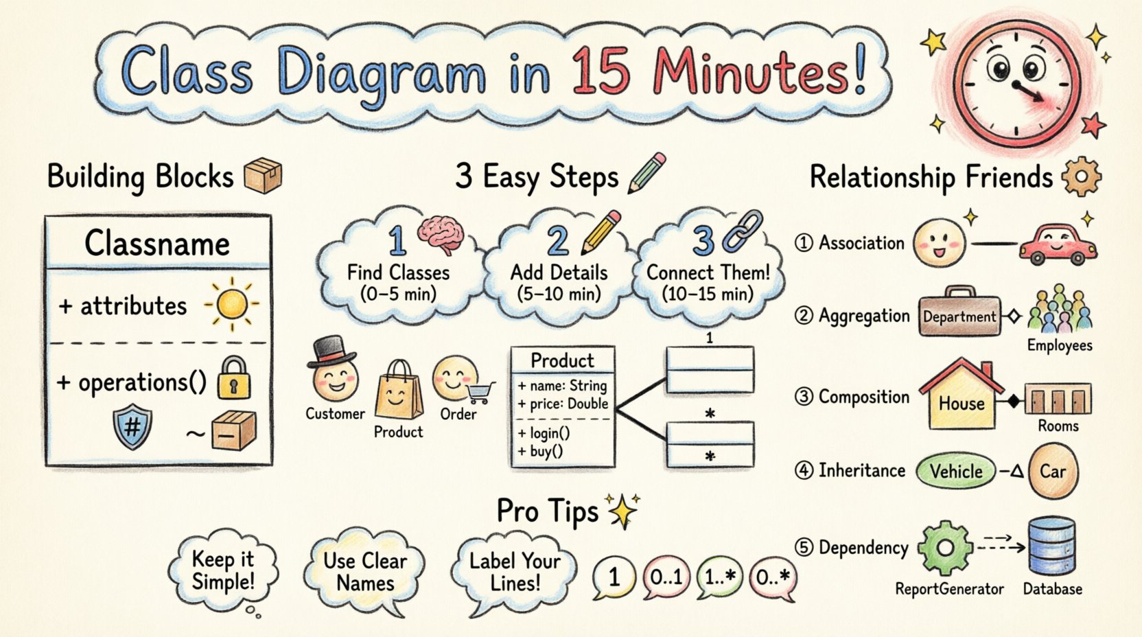
Understanding the Core Components 🧱
Before drawing lines, you must understand the building blocks. A class diagram is composed of specific elements. Each element carries a specific meaning within the Unified Modeling Language (UML) standard. Skipping this foundation often leads to ambiguous diagrams that confuse readers later.
- Class: The fundamental unit. It represents a category of objects with similar characteristics and behaviors.
- Attributes: The data held within a class. These are the properties that define the state.
- Operations: The methods or functions available to interact with the data.
- Visibility: Indicates accessibility. Common symbols include + for public, – for private, and # for protected.
When defining a class, consistency is key. Use nouns for classes and verbs for operations. Attributes should describe the state. For example, if you have a Customer class, attributes might include name or email. Operations might include register or login.
Visibility and Modifiers
Control over access is critical for encapsulation. You must decide how much of the internal state is exposed. Here is a quick reference for standard visibility symbols:
| Symbol | Name | Access Level |
|---|---|---|
| + | Public | Accessible from anywhere |
| – | Private | Accessible only within the class |
| # | Protected | Accessible within the class and subclasses |
| ~ | Package | Accessible within the same package |
Using these symbols correctly prevents confusion during the implementation phase. It signals to other developers which parts of the code are stable and which are internal implementation details.
The 15-Minute Workflow ⏱️
Time management is essential when modeling. A lengthy design session can lead to diminishing returns. The goal is to capture the critical structure without getting bogged down in minor details. Divide your time into three distinct phases. This ensures you move from concept to structure efficiently.
Phase 1: Brainstorming and Identification (0-5 Minutes) 🧠
Start with the problem domain. Do not think about code yet. Think about the real-world entities involved. Read the requirements or functional specifications. Identify the nouns. These nouns are likely to become your classes.
- Read through the user stories or use cases.
- List every significant entity mentioned.
- Filter out generic terms like
ManagerorSystemunless they have specific responsibilities. - Group related entities together.
For instance, in an e-commerce scenario, you might identify Product, Order, Customer, and Payment. These are your candidates. Write them down. You will verify their necessity in the next phase.
Phase 2: Defining Structure and Attributes (5-10 Minutes) 📝
Now, flesh out the classes. For each candidate, define the necessary attributes. Ask yourself: “What information does this entity hold?” Keep the list focused on what is needed for the current scope. Avoid adding attributes for features you might need in the future.
- Customer:
id,name,address,email. - Product:
sku,price,description,stock. - Order:
orderId,date,totalAmount.
Next, define the operations. Ask: “What actions can this entity perform?” or “What actions does it trigger?”
- Customer:
placeOrder(),updateProfile(). - Order:
calculateTotal(),cancel().
Apply visibility modifiers. Make attributes private by default. Expose public operations that are part of the interface. This discipline keeps the design clean and modular.
Phase 3: Establishing Relationships (10-15 Minutes) 🔗
The final phase connects the classes. Relationships define how objects interact. This is the most critical part of the diagram. Incorrect relationships lead to tight coupling and maintenance nightmares. Review the interactions between your entities.
- Does a
Customerhave multipleOrders? - Does an
OrdercontainProducts? - Does a
Paymentdepend on anOrderbeing valid?
Draw lines between the classes. Label them clearly. Use the appropriate relationship type. Do not guess. If you are unsure, refer to the detailed relationship guide below.
Deep Dive into Relationships 🧩
Relationships define the semantics of your model. They tell the story of how data flows and how objects depend on one another. There are five primary types you need to master. Understanding the distinction between them is vital for an accurate representation.
1. Association
Association represents a structural relationship between two classes. It implies that objects of one class are linked to objects of another. It is the most generic relationship type.
- Example: A
Driverdrives aCar. - Direction: Can be unidirectional or bidirectional.
- Labeling: Often labeled with the role name (e.g., “drives”).
Association lines are solid lines. If the relationship is bidirectional, you do not need arrowheads on either end. If unidirectional, place an arrowhead on the class that navigates to the other.
2. Aggregation
Aggregation is a specialized form of association. It represents a “has-a” relationship where the part can exist independently of the whole. It is often described as a weak relationship.
- Example: A
DepartmenthasEmployees. - Logic: If you delete the
Department, theEmployeestill exists. - Visual: A hollow diamond on the whole side.
This relationship is useful for modeling collections. It indicates that the container manages the lifecycle of the collection, but not the individual items within it.
3. Composition
Composition is a strong form of aggregation. It represents a “part-of” relationship where the part cannot exist without the whole. The lifecycle is dependent.
- Example: A
HousehasRooms. - Logic: If you delete the
House, theRoomsare destroyed. - Visual: A filled diamond on the whole side.
Use composition when the child object is exclusive to the parent. This is common in data structures where an object is created and destroyed with its container. It enforces a strict boundary of ownership.
4. Inheritance (Generalization)
Inheritance allows a class to acquire the properties and behaviors of another class. It promotes code reuse and establishes a hierarchy. The subclass is a specialized version of the superclass.
- Example:
Vehicleis the superclass.CarandBikeare subclasses. - Logic: A
Caris aVehicle. - Visual: A solid line with a hollow triangle arrow pointing to the superclass.
Be careful not to create deep hierarchies. Keep the hierarchy shallow to maintain readability. If a class inherits too much, it becomes brittle and difficult to maintain.
5. Dependency
Dependency is a usage relationship. It indicates that a change in one class may affect another. It is often temporary or transient.
- Example: A
ReportGeneratoruses aDatabaseConnection. - Logic: If the
DatabaseConnectionchanges, theReportGeneratormight break. - Visual: A dashed line with an open arrow.
Dependency is the most fragile relationship. It implies a temporary association. It is often resolved through method parameters or local variables. Minimize dependencies to reduce coupling.
Cardinality and Multiplicity
Relationships are rarely one-to-one. You must specify how many instances participate in the relationship. This is known as cardinality or multiplicity. It clarifies the rules of the system.
- 1: Exactly one instance.
- 0..1: Zero or one instance.
- 1..*: One or more instances.
- 0..*: Zero or more instances.
Applying these constraints prevents logical errors. For example, stating that a Customer has 0..1 Address implies they may not have one. Stating that an Order has 1..* Items implies an order cannot be empty.
Best Practices for Clean Models 🌟
A well-structured diagram is self-explanatory. It requires minimal annotation to be understood. Adhering to established conventions makes collaboration easier. Follow these guidelines to maintain high quality.
Keep it Simple
Do not include every single attribute in existence. Focus on the data relevant to the current context. If a diagram has fifty classes, it is likely too complex. Break it down into subsystems or packages. Use compartmentalization to hide unnecessary details.
Consistent Naming Conventions
Naming is a communication tool. Use clear, descriptive names. Avoid abbreviations unless they are industry standard. Classes should be nouns. Operations should be verbs. Attributes should describe the state.
- Bad:
cust,getInfo,val. - Good:
Customer,fetchData,value.
Respect the Law of Demeter
Objects should only talk to their immediate friends. Avoid calling methods on objects returned by other methods. This reduces coupling. If you find yourself navigating deep into object graphs, reconsider your design. It may indicate that the classes are too tightly coupled.
Review for Cycles
Check for circular dependencies. If Class A depends on Class B, and Class B depends on Class A, you may have a design issue. This often leads to initialization errors in code. Break the cycle by introducing an interface or a mediator.
Common Mistakes to Avoid 🚫
Even experienced designers make mistakes. Being aware of common pitfalls helps you avoid them. Review your work against this checklist before finalizing the model.
- Mixing Responsibilities: A class should do one thing well. If a class handles both database access and user interface logic, split it.
- Ignoring Interfaces: Relying too heavily on concrete classes makes testing difficult. Use interfaces where possible to define contracts.
- Overusing Inheritance: Favor composition over inheritance. Inheritance creates tight coupling. Composition offers more flexibility.
- Missing Multiplicity: Leaving relationship lines unlabeled leaves the meaning ambiguous. Always specify cardinality.
- Static vs. Instance: Do not confuse static members with instance members. Static members belong to the class itself, not specific instances. Represent this clearly in your notation.
Final Thoughts on Design 🚀
Creating a class diagram is an exercise in abstraction. You are translating complex requirements into a simplified visual representation. The goal is not perfection, but clarity. A diagram that aids understanding is successful.
Remember that diagrams are living documents. As requirements change, the model must evolve. Treat it as a map that guides the development process. Revisit it during code reviews to ensure the implementation matches the design.
By following a structured approach, you can produce a high-quality model in a short time. Focus on the core entities, define clear relationships, and apply standard notation. This foundation supports scalable and maintainable software architecture. Keep the design simple, the naming clear, and the relationships logical.