One of the most persistent challenges in software development is the disconnect between what stakeholders want and what developers build. Business requirements often exist in the form of narratives, user stories, or high-level documents. However, the actual system relies on concrete structures: classes, attributes, and relationships. This translation process is not merely administrative; it is the foundation of a robust architecture. When the bridge between business needs and technical implementation is weak, the resulting system often suffers from rigidity, ambiguity, or failure to meet user expectations.
This guide explores the systematic approach to converting business requirements into functional class diagrams. We will examine the necessary steps, the underlying principles of object-oriented design, and how to ensure traceability from the initial request to the final code structure. By focusing on clarity and precision, teams can reduce rework and create systems that align with business goals.
🔍 Understanding Business Requirements
Before drawing a single box or line, one must understand the source material. Business requirements define the problem space. They describe what the system must do, not necessarily how it will do it. These requirements usually come from interviews, workshops, or existing documentation.
Effective analysis involves categorizing these inputs. Not all requirements carry the same weight or structural implication. To facilitate this analysis, consider the following categories:
- Functional Requirements: Specific behaviors or functions the system must perform. These are the primary drivers for class creation.
- Non-Functional Requirements: Constraints such as performance, security, or reliability. While these do not always map to specific classes, they influence design decisions like interface definitions.
- Business Rules: Conditions that govern operations. For example, “A discount cannot be applied to items already on sale.” These often become validation logic within methods or attributes.
- Entities: The nouns identified in the requirements. These are the strongest candidates for class definitions.
When reviewing a requirement document, look for repeated nouns. If the word “Customer” appears ten times in different contexts, it is likely a central entity in the system. However, context matters. A “Customer” in a sales context may differ from a “Customer” in a support context. Distinguishing these nuances is the first step in accurate modeling.
📐 The Anatomy of a Class Diagram
Once the requirements are understood, the focus shifts to representation. A class diagram is a static view of the system structure. It visualizes the classes, their attributes, methods, and the relationships between them. Unlike a sequence diagram, which shows time-based interaction, a class diagram shows the skeletal framework.
To create a functional diagram, you must be familiar with the core components:
- Class: A blueprint for creating objects. It encapsulates data and behavior.
- Attributes: The data properties stored within a class (e.g.,
customerName,orderDate). - Methods: The actions the class can perform (e.g.,
calculateTotal(),applyDiscount()). - Visibility: Indicators like
+(public),-(private), or#(protected) that define accessibility. - Relationships: Connections between classes, including Association, Aggregation, Composition, and Inheritance.
Understanding these elements is not enough; one must know when to apply them. Overusing inheritance can lead to fragile hierarchies, while excessive composition can create complex coupling. The goal is to reflect the business domain accurately without introducing unnecessary complexity.
🔄 The Translation Workflow
Translating requirements into diagrams is an iterative process. It involves moving from abstract text to concrete structure. The following workflow provides a structured path for this transition.
1. Extract Key Entities
Read through the functional requirements and highlight every noun that represents a distinct concept in the business domain. These are your initial class candidates. For example, if a requirement states, “The system must track every invoice generated,” the words “invoice” and “system” are candidates. “System” is usually too abstract, but “Invoice” is a strong candidate for a class.
2. Identify Attributes and Methods
Once the nouns are identified, determine what data they hold and what actions they support. Look for verbs in the requirements. If a requirement says, “The system must validate the invoice amount against the budget,” the class Invoice likely needs a method validateAmount() and an attribute budgetLimit.
3. Define Relationships
How do these entities interact? This is often the most difficult part. Relationships answer questions like: Does an Invoice belong to a Customer? Can a Customer have multiple Invoices? This defines cardinality (one-to-one, one-to-many).
Common relationship types include:
- Association: A general link between two objects.
- Aggregation: A whole-part relationship where the part can exist independently.
- Composition: A strong whole-part relationship where the part cannot exist without the whole.
- Inheritance: A specialization relationship where a child class inherits from a parent.
4. Validate Against Non-Functional Requirements
Check if the proposed structure supports performance and security needs. For instance, if data retrieval must be fast, consider how attributes are indexed or how relationships are navigated. While a class diagram does not show implementation details, it should not contradict performance constraints.
📊 Mapping Requirements to Structure
To visualize how textual requirements transform into structural elements, consider the following table. This demonstrates the direct line from a business rule to a technical artifact.
| Business Requirement | Key Entity | Proposed Class | Key Attribute | Key Method |
|---|---|---|---|---|
| A user must be able to register a new account. | Account | UserAccount |
emailAddress, passwordHash |
register() |
| Orders must be linked to a specific inventory item. | Order, Inventory | Order, InventoryItem |
quantity, sku |
checkAvailability() |
| The system calculates tax based on the region. | Region, Tax | Order, Region |
taxRate, regionCode |
calculateTax() |
| A discount is applied only if the order total exceeds $100. | Discount | PromotionRule |
minimumAmount, discountPercentage |
applyTo() |
This mapping ensures that every class has a business justification. If you create a class without a corresponding requirement, it may be dead code. If a requirement has no class representation, the functionality might be lost.
🧪 Example Scenario: E-Commerce System
Let us apply this workflow to a hypothetical e-commerce scenario. Imagine the requirements state: “Customers can browse products. They add items to a cart. They place an order. The order is shipped to their address.”
Step 1: Entity Identification
Scanning the text reveals the following nouns:
- Customer
- Product
- Cart
- Order
- Address
These become the primary classes.
Step 2: Attribute and Method Definition
For Customer, we need contact details and a list of orders. For Product, we need price and stock levels. For Order, we need a list of items and a shipping address.
Customerattributes:customerId,name,email.Productattributes:productId,price,description.Orderattributes:orderId,orderDate,totalAmount.
Step 3: Relationship Mapping
How do they connect? A customer places multiple orders (One-to-Many). An order contains multiple products (Many-to-Many, resolved via an OrderItem class). An order is shipped to one address.
This logic dictates the lines drawn between the boxes. The relationship between Order and Product is often resolved by introducing an OrderItem class, which holds the specific quantity and price at the time of purchase.
⚠️ Common Pitfalls in Translation
Even with a clear process, errors can occur. Recognizing these pitfalls helps maintain the integrity of the model.
1. Over-Engineering
It is easy to create a class structure that anticipates future needs rather than current requirements. While foresight is valuable, adding unnecessary complexity now can hinder development later. Stick to what is required for the immediate scope.
2. Ignoring Data Types
A class diagram is not just about names. Attributes need types. Using a generic “String” for a date is a mistake. It should be Date or DateTime. Using an integer for currency is risky without considering decimal precision. Correct typing prevents runtime errors.
3. Misinterpreting Relationships
Confusing aggregation with composition is common. If a House contains Rooms, the rooms usually cannot exist without the house (Composition). If a University has Departments, a department might exist even if the university changes (Aggregation). Getting this wrong changes the lifecycle management of the objects.
4. Neglecting Identity
Every class should have a unique identifier, or primary key. Without this, tracking instances becomes difficult. In the diagram, this is often marked as a key attribute.
🛠️ Best Practices for Clarity
To ensure the diagram remains useful throughout the project lifecycle, follow these guidelines.
- Maintain Traceability: Keep a document linking requirements to specific classes. If a requirement changes, you know exactly which part of the diagram to update.
- Keep it High-Level First: Start with the core entities. Add details like specific methods only after the structure is solid. Do not clutter the initial view with implementation logic.
- Use Standard Notation: Adhere to standard modeling conventions so that any developer on the team can read the diagram without a legend.
- Review with Stakeholders: Even though it is technical, show the diagram to business users. Ask them, “Does this object represent what you meant by ‘Invoice’?” This validates the translation.
- Iterate: The first draft is rarely the final one. As development progresses, new requirements emerge. Update the diagram to reflect the evolving system.
🔗 Ensuring Traceability
Traceability is the ability to track a requirement from its origin through to implementation. In the context of class diagrams, this means every class should ideally map back to a requirement.
During the design review, ask the following questions:
- Does every class serve a business purpose?
- Is there a requirement that justifies the existence of this relationship?
- Are all required attributes present?
If a class has no link to a requirement, it is a candidate for removal. This practice keeps the codebase lean and focused on value delivery.
🔄 Iterative Refinement
Software design is rarely linear. The initial translation is a hypothesis. As developers begin coding, they often discover nuances that the requirements document missed. For example, a requirement might say “Store user information,” but during implementation, it becomes clear that user information changes over time and requires an audit log.
This discovery loop requires updating the class diagram. The diagram is a living document. It should evolve alongside the code. If the code changes, the diagram must change. If the requirements change, the diagram must change. This synchronization is critical for long-term maintainability.
📝 Summary of Key Takeaways
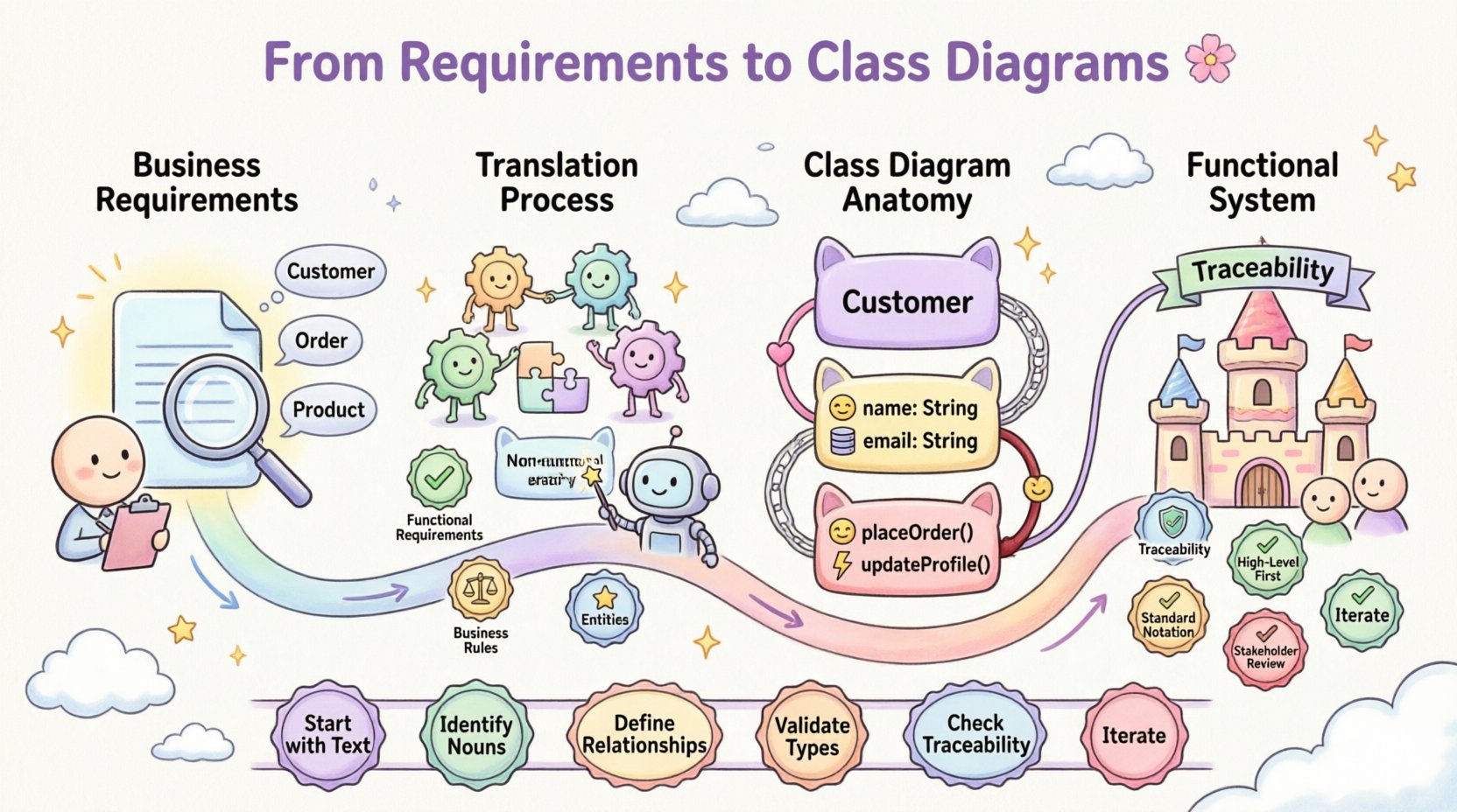
- Start with Text: Business requirements are the source of truth.
- Identify Nouns: These are your primary class candidates.
- Define Relationships: Understand how entities interact to model data flow correctly.
- Validate Types: Ensure attributes have appropriate data types.
- Check Traceability: Ensure every class serves a defined business need.
- Iterate: Treat the diagram as a draft that improves with feedback.
By following a disciplined approach to translation, teams can minimize the gap between business intent and technical reality. The result is a system that is easier to understand, easier to modify, and aligned with organizational goals. This alignment reduces risk and increases the value delivered to the end user.
The process requires attention to detail and a willingness to challenge assumptions. It is not about drawing pretty pictures; it is about structuring logic that supports business operations. When done correctly, the class diagram becomes a communication tool that bridges the divide between the business and the technical teams.
Remember, the goal is functional accuracy. A diagram that looks complex but fails to model the requirements is less useful than a simple diagram that works perfectly. Focus on clarity, correctness, and alignment.