Designing complex systems requires clear communication. The Unified Modeling Language (UML) provides a standardized way to visualize system behavior. Among its various diagram types, the Interaction Overview Diagram stands out for its ability to combine the high-level flow of an Activity Diagram with the detailed object interactions of a Sequence Diagram. However, creating these diagrams is not merely about drawing boxes and lines. It is about ensuring logical consistency, traceability, and clarity.
When logic gaps appear in an Interaction Overview Diagram, the consequences can ripple through development and testing phases. Misunderstandings lead to implementation errors, which in turn cause delays and increased costs. This guide provides a structured approach to identifying and resolving these issues. We will explore common pitfalls, validation strategies, and methods to ensure your diagrams accurately reflect the intended system behavior without relying on specific tooling features.
🧐 Understanding the Interaction Overview Diagram
Before troubleshooting, it is essential to understand what constitutes a valid Interaction Overview Diagram. Unlike a standard Activity Diagram, which focuses on control flow and state changes, the Interaction Overview Diagram integrates interaction fragments. It acts as a bridge between the static structure of the system and the dynamic behavior of its components.
Key elements include:
- Control Nodes: Represent decision points, forks, joins, and initial/final states.
- Interaction Fragments: Boxes that encapsulate sequence diagrams or other interaction details.
- Objects and Lifelines: The entities participating in the interaction within the fragments.
- Messages: The flow of information between objects inside the fragments.
When troubleshooting, you are essentially auditing the path from the initial node to the final node. Every decision point must have a defined outcome. Every interaction fragment must have a clear entry and exit point. If these connections are ambiguous, the diagram fails its primary purpose: communication.
🕵️♂️ Identifying Common Logic Gaps
Logic gaps often arise from assumptions made during the design phase. A designer might assume a user will always click a button, or that a database query will always succeed. These assumptions create gaps when the diagram is subjected to real-world conditions. Below are the most frequent categories of logic errors encountered during reviews.
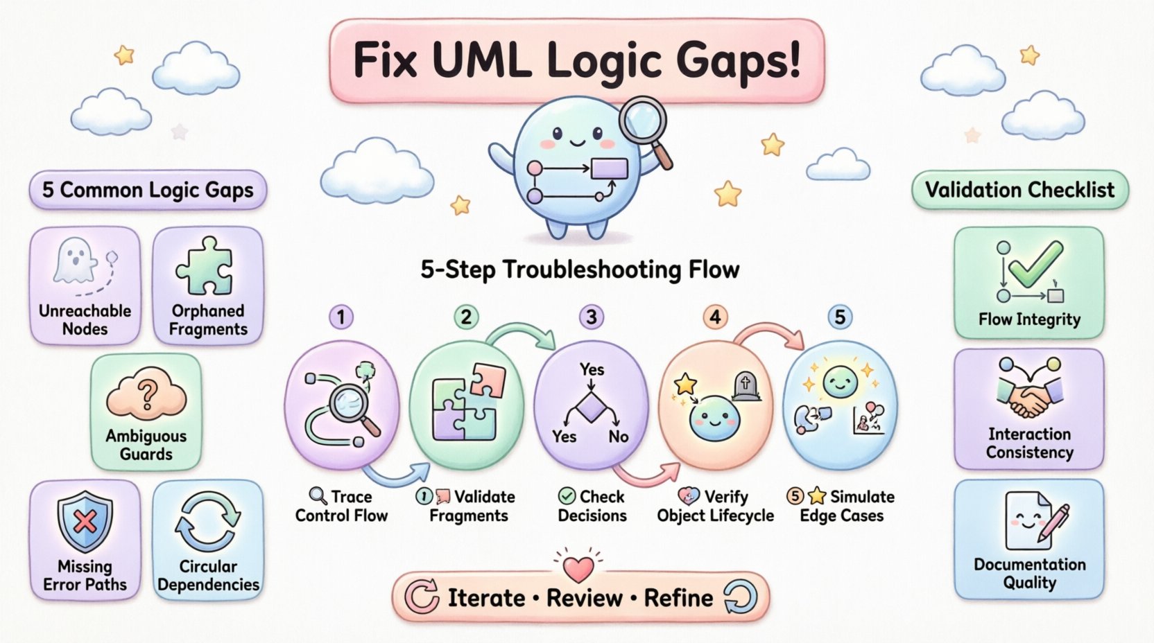
1. Unreachable Nodes
Sometimes, a specific node or interaction fragment is drawn but cannot be reached from the initial node. This often happens when control flow arrows are misdirected or when decision guards are too restrictive. An unreachable node implies dead code in the actual system, which is a waste of resources.
2. Orphaned Interaction Fragments
An interaction fragment that has an entry point but no exit point creates a loop or a dead end. If the flow enters a sequence of events and cannot determine when to return to the overview, the system hangs. Conversely, if a fragment is entered but never returns control to the main flow, subsequent steps are never executed.
3. Ambiguous Decision Guards
Decision nodes require clear conditions. If a guard condition is vague, such as “if valid” without defining what constitutes valid, the diagram becomes subjective. Different developers may interpret the condition differently, leading to inconsistent implementations.
4. Missing Error Handling Paths
Many diagrams focus solely on the “happy path”. They show what happens when everything works perfectly. However, troubleshooting must include negative paths. What happens if a service times out? What if a user cancels an operation? If these paths are missing, the diagram does not represent the full system logic.
5. Circular Dependencies
Control flows should generally move forward toward a final node. Circular dependencies where the flow loops indefinitely without a break condition indicate a logic error. This is particularly common when trying to model retry mechanisms or user confirmation loops.
📊 Common Logic Issues and Fixes
To facilitate a quick review, the following table outlines common issues and their corresponding corrective actions. This checklist serves as a reference during the troubleshooting process.
| Issue Type | Indicator | Corrective Action |
|---|---|---|
| Unreachable Node | No incoming arrow from start or previous decision | Trace flow from start. Add missing arrows or remove the orphaned node. |
| Dead End Fragment | Entry exists, no exit to next node | Ensure every fragment has a return path or connects to a final node. |
| Unclear Guards | Labels like “ok” or “yes” without context | Define specific conditions (e.g., “if status == 200”). |
| Missing Error Path | No “X” or “Error” label on decision nodes | Add alternative branches for exception handling scenarios. |
| Infinite Loop | Flow returns to previous node without exit condition | Add a counter or a specific break condition to the loop. |
| Object State Conflict | Object appears in two states simultaneously | Review object lifelines. Ensure state changes are sequential. |
🔍 Step-by-Step Troubleshooting Methodology
Fixing logic gaps requires a systematic approach. Ad-hoc checks often miss subtle errors. Use the following methodology to audit your diagram thoroughly.
Step 1: Trace the Control Flow
Start at the initial node. Follow every arrow physically, whether on screen or paper. Do not skip steps. Ask yourself: “If I were a program executing this, what would happen next?” If you hit a wall where the path is unclear, you have found a gap. Document every junction where a choice must be made.
Step 2: Validate Interaction Fragments
Open each interaction fragment contained within the overview. Treat them as mini-sequence diagrams. Do they start with a message? Do they end with a return or a final state? Ensure that the variables passed from the overview diagram match the parameters required inside the fragment. Mismatches here cause runtime errors.
Step 3: Check Decision Node Coverage
For every decision diamond, count the outgoing edges. If there are two edges, there should be two conditions (e.g., True and False). If there are three, there must be three distinct paths. Ensure that all possible outcomes are covered. If a condition is missing, the diagram is incomplete.
Step 4: Verify Object Lifecycle
Objects must be created before they are used and destroyed after they are no longer needed. Check the lifelines in the fragments. If an object is referenced before it is created, the logic is flawed. If it persists indefinitely without a destroy message, it suggests a memory leak in the design.
Step 5: Simulate Edge Cases
Do not just simulate the standard user journey. Simulate the edge cases. What if the input is null? What if the connection is lost? Run these scenarios through the diagram. If the diagram does not account for these inputs, you must add the necessary logic branches.
🤝 Collaboration and Peer Review
One of the most effective ways to find logic gaps is to have someone else review the diagram. A fresh pair of eyes can spot inconsistencies that the creator overlooks due to familiarity. When conducting a peer review, focus on the following aspects:
- Clarity of Notation: Ensure standard UML symbols are used correctly. Non-standard symbols create confusion.
- Consistency: Do naming conventions for objects and messages remain consistent throughout the diagram?
- Completeness: Does the diagram cover all requirements? Cross-reference the diagram with the use case list.
- Readability: Is the layout logical? Arrows should not cross unnecessarily. Group related interactions together.
During the review session, ask the designer to walk you through the diagram. Explain the flow from start to finish. Often, explaining the logic aloud reveals gaps that were invisible during silent review. If the designer hesitates or has to guess at a step, that is a red flag.
🛡️ Validation Checklists
Before finalizing the diagram, run through this validation checklist. This ensures that no logic gap slips through the cracks.
Flow Integrity
- ✅ Is there exactly one initial node?
- ✅ Is there at least one final node?
- ✅ Can every node be reached from the initial node?
- ✅ Can every node reach a final node (no dead ends)?
- ✅ Are all decision nodes fully covered (all outcomes represented)?
Interaction Consistency
- ✅ Do all interaction fragments have valid entry and exit points?
- ✅ Are messages within fragments consistent with object states?
- ✅ Are parameters passed correctly between overview and fragments?
- ✅ Do lifelines show correct creation and destruction?
Documentation Quality
- ✅ Are all decision guards clearly labeled?
- ✅ Is the diagram layout clean and uncluttered?
- ✅ Is the version number documented?
- ✅ Are the authors and reviewers listed?
🔄 Iterative Refinement
Design is rarely a one-time activity. It is an iterative process. After the first round of troubleshooting, you will likely need to refine the diagram. This might involve splitting a large interaction fragment into smaller ones for clarity, or adding more detail to a decision node. Do not be afraid to redraw the diagram if the logic has changed significantly.
Refinement also involves updating the diagram as the system evolves. If the requirements change, the diagram must change with them. An outdated diagram is worse than no diagram at all, as it leads to false confidence in the system design. Schedule regular reviews to ensure the diagram remains aligned with the current implementation.
🧩 Handling Complex Scenarios
Some systems involve complex logic that is difficult to represent in a single diagram. In these cases, consider the following strategies:
- Decomposition: Break the large diagram into smaller sub-diagrams. Link them using interaction references.
- Commenting: Use notes to explain complex logic that cannot be easily visualized with standard symbols.
- Standardization: Adopt a standard for handling common patterns, such as error handling or logging, to reduce clutter.
When dealing with concurrency, ensure that the interaction overview diagram reflects the correct synchronization points. If multiple threads are involved, the diagram must show where they join and where they fork. Failing to model concurrency correctly can lead to race conditions in the actual code.
🚀 Moving Forward
Creating a robust UML Interaction Overview Diagram is about precision. It requires you to think like a computer, tracing every possible path and ensuring that the logic holds up under scrutiny. By following the troubleshooting steps outlined in this guide, you can identify and fix logic gaps before they cause confusion in the development team.
Remember that the goal is clarity. If a stakeholder looks at the diagram and understands the flow without needing an explanation, you have succeeded. If they ask questions about how a specific path works, you have found a gap. Keep refining, keep reviewing, and keep ensuring that the logic is sound. This diligence pays off in the stability and reliability of the final product.
Invest time in the design phase to save time in the development phase. A well-troubled diagram acts as a blueprint that guides the entire team. It reduces ambiguity and ensures that everyone is working from the same understanding of the system behavior.