Modeling complex systems requires precision. In the field of Requirements Engineering, the choice of notation directly impacts clarity, traceability, and implementation accuracy. Two of the most prevalent behavioral modeling techniques are the UML Sequence Diagram and the UML Interaction Overview Diagram. While both describe system interactions, they serve distinct purposes within the architectural hierarchy.
Requirements engineers often face the challenge of communicating high-level workflows alongside detailed transactional logic. Relying solely on one diagram type can lead to ambiguity or excessive complexity. This guide provides a definitive analysis of these two modeling artifacts, helping you select the appropriate tool for specific engineering contexts.
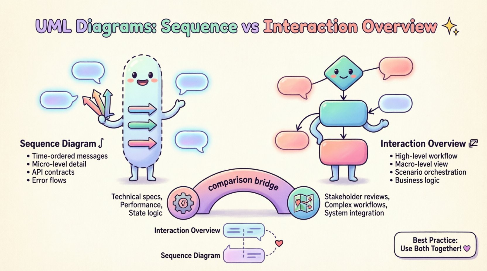
📜 Understanding UML Sequence Diagrams
The Sequence Diagram is the standard for modeling time-ordered interactions between objects or participants. It focuses on the how of a specific scenario, detailing the exact order of message exchanges.
Core Components
- Lifelines: Represent the participants (objects, actors, subsystems) involved in the interaction. These are vertical dashed lines extending from the top.
- Activation Bars: Rectangular boxes placed on lifelines indicating the period during which an object is performing an action or waiting for a response.
- Messages: Arrows connecting lifelines. These can be synchronous (solid line with filled arrowhead), asynchronous (dashed line with open arrowhead), or return messages (dashed line).
- Combined Fragments: Boxes that group messages and define control flow logic such as
opt(optional),alt(alternative),loop(iteration), andbreak.
Strengths in Requirements Engineering
- Temporal Precision: Captures the exact sequence of events, which is critical for state-sensitive requirements.
- Interface Definition: Clearly defines the API contracts between components, specifying input parameters and return values.
- Error Handling: Excellent for modeling exception flows using combined fragments, ensuring robust requirements for failure scenarios.
However, Sequence Diagrams have limitations when the scope expands beyond a single use case. A complex system with hundreds of interactions may result in a diagram that is too long to read effectively. This is where the Interaction Overview Diagram becomes essential.
🔗 Understanding UML Interaction Overview Diagrams
The Interaction Overview Diagram is a specialized activity diagram that focuses on high-level control flow. Instead of detailing every message exchange, it represents interactions as black-box nodes or frames. It answers the question: Which interaction scenarios occur, and in what order?
Core Components
- Interaction Nodes: Frames or rectangles representing specific Sequence Diagrams. These act as sub-graphs within the overview.
- Control Flow Edges: Directed arrows connecting interaction nodes, similar to flowchart logic.
- Decision Nodes: Diamond shapes that direct flow based on boolean conditions derived from system state.
- Fork/Join Nodes: Symbols indicating parallel processing or synchronization points within the workflow.
- Initial and Final Nodes: Standard start and end points for the interaction flow.
Strengths in Requirements Engineering
- Macro-Level Visibility: Provides a map of the system behavior without getting bogged down in message details.
- Modularity: Allows you to group related scenarios. You can link to a specific Sequence Diagram for the “Checkout Process” without cluttering the main view.
- Logic Orchestration: Ideal for modeling business rules that dictate which sequence of events should occur based on user choices or system states.
⚖️ Key Differences: A Structured Comparison
To understand when to apply each diagram, we must look at their structural and functional differences. The following table outlines the distinctions relevant to system design and requirements analysis.
| Feature | Sequence Diagram | Interaction Overview Diagram |
|---|---|---|
| Primary Focus | Message exchange and timing between objects. | Control flow between interaction scenarios. |
| Granularity | Micro: Details individual messages and parameters. | Macro: Treats interactions as atomic blocks. |
| Complexity Handling | Can become unwieldy with many parallel threads. | Manages complexity by abstracting sub-processes. |
| Use Case Coverage | Typically models one specific scenario or use case. | Models multiple scenarios and their transitions. |
| Control Flow | Uses combined fragments (alt, opt, loop). | Uses standard activity flow (forks, decisions). |
| Readability | High for technical implementation details. | High for business logic and workflow overview. |
| Traceability | Links directly to class and component interfaces. | Links to high-level requirements and use cases. |
🚦 When to Use Which Diagram
Selecting the right diagram depends on the stage of the requirements lifecycle and the audience for the documentation. A requirements engineer must align the modeling technique with the stakeholder’s needs.
Scenarios for Sequence Diagrams
- Interface Specification: When defining the exact contract between two software modules.
- Performance Analysis: When timing and latency of specific message exchanges are critical requirements.
- State Transitions: When the state of an object changes based on a specific sequence of inputs.
- Technical Design Reviews: When presenting to software architects or developers who need to know exactly what data is passed.
Scenarios for Interaction Overview Diagrams
- Workflow Visualization: When explaining the end-to-end process of a business function to non-technical stakeholders.
- Scenario Management: When a single use case involves branching paths that require different sequences.
- System Integration: When modeling how different subsystems hand off control to one another.
- Complex Logic Flows: When loops, parallel threads, or conditional branching are too complex for a single sequence diagram.
🔗 Integrating Both for Comprehensive Modeling
In mature requirements engineering practices, these diagrams are not mutually exclusive. They are complementary artifacts. The Interaction Overview Diagram acts as a table of contents for the detailed Sequence Diagrams.
The Hierarchy of Behavior
Consider a workflow where a user submits a request. The Interaction Overview Diagram outlines the steps:
- 1. Receive Request
- 2. Validate Data
- 3. Process Transaction
- 4. Generate Report
Each of these steps can be linked to a separate Sequence Diagram. This keeps the high-level view clean while preserving the depth required for implementation. This structure supports the principle of separation of concerns, allowing different teams to focus on different levels of abstraction.
Traceability Matrix Alignment
Maintaining traceability between requirements and diagrams is crucial. A requirements ID (e.g., REQ-101) should link to the specific Sequence Diagram that implements the logic. The Interaction Overview Diagram then links to the REQ-101 node to show where it fits in the broader process.
This creates a traceability chain:
- High-Level Requirement
- Interaction Overview Node
- Sequence Diagram Fragment
- Code Unit (via API contract)
🛠️ Common Pitfalls in Modeling
Even with the right tools, requirements engineers often make mistakes that reduce the utility of the diagrams. Understanding these pitfalls helps maintain diagram integrity.
Pitfall 1: Over-Modeling in Sequence Diagrams
Attempting to model an entire system lifecycle in a single Sequence Diagram leads to a vertical scroll that exceeds the monitor’s height. This makes the diagram unreadable. Break the diagram into logical chunks.
Pitfall 2: Ignoring Asynchronous Messages
Sequence Diagrams often default to synchronous calls. However, modern systems rely heavily on asynchronous events (e.g., message queues, webhooks). Failing to represent this can lead to implementation delays during the coding phase.
Pitfall 3: Circular References in Overviews
In Interaction Overview Diagrams, creating circular dependencies between interaction nodes can cause confusion. While loops are valid, ensure the exit condition is clearly defined to prevent infinite modeling loops.
Pitfall 4: Mixing Levels of Abstraction
Do not mix detailed message parameters with high-level control flow in the same diagram. If you need to show data structures, do so in the Sequence Diagram. If you need to show logic flow, do so in the Overview Diagram.
📏 Best Practices for Requirements Engineers
To maximize the value of UML modeling, adhere to the following guidelines. These practices ensure consistency across documentation and facilitate better communication.
1. Use Standard Notation
Adhere strictly to the Unified Modeling Language (UML) standard. Deviating from standard symbols (e.g., using custom icons for decision nodes) creates barriers for anyone reading the document who is not familiar with your internal conventions.
2. Keep Labels Concise
Diagram labels should be brief. Use full sentences in the accompanying text if necessary, but keep the diagram elements clean. A message label like validateUserCredentials() is better than validate user credentials and check if they are correct.
3. Define Scope Explicitly
Every diagram should have a defined scope. Label the top of the diagram with the specific use case or requirement ID it addresses. This prevents ambiguity about which part of the system is being modeled.
4. Leverage Combined Fragments Correctly
Use opt for optional behavior and alt for mutually exclusive paths. Do not overuse loop for simple iterations. Clarity in control flow is more important than capturing every theoretical edge case.
5. Version Your Models
Requirements change. Your diagrams must change with them. Maintain version control for your model files. A diagram from a previous iteration should not be mixed with current requirements.
🧩 Advanced: Combining with State Machines
While Sequence and Interaction Overview Diagrams excel at behavior, they do not fully capture object state. For requirements that depend heavily on state changes (e.g., an order that can be “Pending”, “Shipped”, or “Cancelled”), consider integrating these with State Machine Diagrams.
You can link a specific state transition in a State Machine to an Interaction Overview Node. This ensures that the behavior is not only described but also constrained by the valid states of the entities involved. This integration prevents invalid state transitions from being modeled in the interaction flow.
📝 Conclusion on Modeling Strategy
The choice between an Interaction Overview Diagram and a Sequence Diagram is not a binary decision but a strategic one based on the level of detail required. Sequence Diagrams provide the depth needed for technical implementation, while Interaction Overview Diagrams provide the breadth needed for business alignment.
By mastering the distinction and application of both, requirements engineers can create a documentation set that is both technically rigorous and business-relevant. This duality ensures that the system is built correctly and builds the right system.
Remember that diagrams are communication tools, not just design artifacts. Their primary value lies in how well they convey intent to developers, testers, and stakeholders. Prioritize clarity over completeness. A diagram that is understood is more valuable than one that is comprehensive but unreadable.
Apply these principles to your next modeling task. Evaluate the complexity of your requirements. If the flow is linear and detailed, reach for the Sequence Diagram. If the flow involves branching logic and multiple scenarios, start with the Interaction Overview Diagram. This disciplined approach will streamline your requirements process and reduce the risk of misinterpretation during development.