


🔹 1. What Is This Diagram?
This is a UML Activity Diagram with Swimlanes, also known as a cross-functional flowchart or swimlane diagram.
✅ Purpose:
To model the end-to-end workflow of a pizza delivery process — from order placement to final delivery — while clearly assigning responsibility, sequence, and decision points to specific roles or systems.
🎯 Key Features:
- Swimlanes (vertical columns) represent actors, roles, or departments.
- Flow of control moves from top to bottom (or left to right), showing chronological order.
- Standard UML notation is used, enhanced with swimlane structure for clarity.
🧩 Participants (Swimlanes / Roles):
💡 Why Swimlanes?
They make it easy to see who does what, where handoffs occur, and where delays or errors might happen — essential for process analysis and improvement.
🔹 2. Step-by-Step Walkthrough of the Process
The diagram flows top to bottom, representing the natural timeline of a pizza delivery.
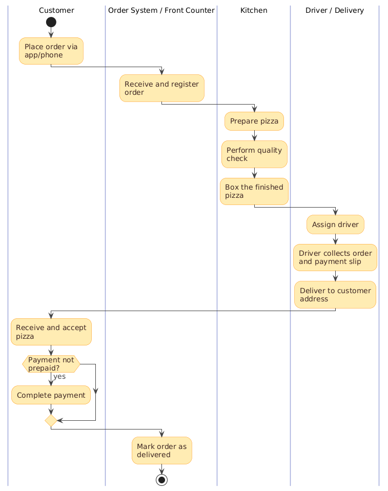
🟢 1. Start: Customer Places Order
- Trigger: Customer places an order via app, phone, or in-person.
- Symbol:
start(filled circle) — the initial node. - Swimlane: Customer
✅ This is the starting point of the entire process.
🟡 2. Order System / Front Counter: Receive & Register Order
- Action: Capture order details (pizza type, toppings, address, payment method).
- System Update: Mark order as “Received” in the system.
- Handoff: Pass order to the Kitchen.
- Arrow: Crosses from Customer → Order System → Kitchen
⚠️ This is a critical handoff — any delay here affects the whole chain.
🔵 3. Kitchen: Prepare the Pizza
- Sub-steps:
- Prepare pizza (dough, sauce, cheese, toppings)
- Perform quality check (inspect appearance, doneness, taste)
- Box the finished pizza
- Swimlane: Kitchen
- Flow: Sequential, no branches
🧠 Tip: “Perform quality check” can be refined to “Inspect & correct if needed” for more precision.
🟣 4. Driver / Delivery: Prepare for Delivery
- Actions:
- Assign driver (based on proximity or availability)
- Driver collects order and payment slip from counter
- Swimlane: Driver / Delivery
- Handoff: From Kitchen → Driver
🔗 This handoff is crucial — if the driver doesn’t get the correct slip, payment issues may arise.
🟠 5. Customer: Receive and Accept Pizza
- Action: Customer receives the delivered pizza.
- Swimlane: Customer
- Decision Point: Is payment not prepaid?
✅ This is the only decision point in the flow — critical for handling cash-on-delivery (COD) cases.
🟤 6. Decision: Was Payment Not Prepaid?
- Condition:
Payment not prepaid? - Yes → Customer completes payment (cash or card).
- No → Skip (already paid via app/card).
🔄 This creates a branching path:
- Yes (COD): Customer pays → system updated
- No (Prepaid): Flow continues directly
📌 Best Practice: Label decision conditions clearly on outgoing arrows, e.g.,
[Yes],[No].
🟦 7. Order System / Front Counter: Mark Order as Delivered
- Action: Update system status to “Delivered”.
- Finalization: Close the order record.
- Swimlane: Order System
✅ Ensures data accuracy and supports reporting, analytics, and audits.
🔴 8. End: Process Complete
- Symbol:
stop(filled circle with border) — the final node. - Swimlane: Not applicable (process end)
✅ All steps complete. The delivery lifecycle ends.
🔹 3. Key UML Activity Diagram Elements Used
🎯 Note: In strict UML, guard conditions should be written on arrows:
[Payment not prepaid], not inside the diamond.
🔹 4. Core Concepts in Swimlane Activity Diagrams
🏗️ Purpose of Swimlane Diagrams
- Visualize who does what, when, and in what order.
- Highlight handoffs, delays, responsibility gaps, and bottlenecks.
- Ideal for multi-department, cross-functional, or software-integrated processes.
🧭 Swimlanes = Responsibility Lanes
- Each lane = one actor or system.
- All actions must be in the correct lane.
- Never draw a kitchen task in the “Customer” lane — violates responsibility boundaries.
🔄 Handoffs: The Critical Points
- Arrows crossing swimlane boundaries = handoffs.
- These are high-risk areas in real-world operations.
- Example:
Kitchen → Driver: If the driver doesn’t receive the correct order or slip, delivery fails.
📈 Linear vs. Complex Flows
- This pizza process is mostly linear → perfect for swimlanes.
- For complex processes (e.g., parallel preparation, multiple delivery routes), consider:
- Forks & Joins (
fork,join) - Sub-activities (if a step is very complex)
- Alternative paths (e.g., “Rush delivery”, “Order canceled”)
- Forks & Joins (
🔹 5. Best Practices & Guidelines
✅ General Best Practices for Swimlane Activity Diagrams
✨ Specific Observations & Suggestions for This Pizza Diagram
🔹 6. Real-World Use Cases
This type of swimlane diagram is invaluable for:
🎯 Example Insight:
If delivery delays are common, this diagram helps identify whether the bottleneck is in driver assignment, collection time, or customer availability.
🔹 7. Summary & Takeaways
✅ Why This Diagram Works:
- Clear, role-based structure.
- Simple, linear flow with one logical exception.
- Perfect example of when swimlanes shine — showing who does what in a multi-step, cross-functional process.
🎯 Key Lessons:
- Swimlanes clarify responsibility — no more “Who’s supposed to do this?”
- Handoffs are where errors happen — monitor them closely.
- Decision points should be simple and actionable — avoid complex logic.
- Use consistent, clear labels — verb + noun, clear conditions.
- Keep it readable — avoid overcrowding; use sub-activities if needed.
📌 Final Tip: How to Create This Diagram in PlantUML
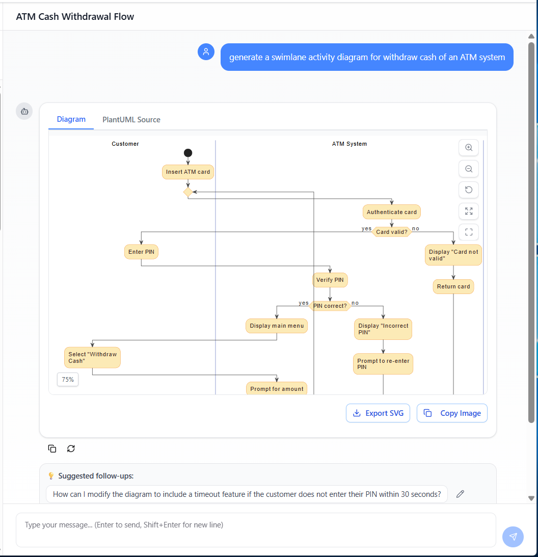
🤖 How to Use Visual Paradigm AI Chatbot to Automate This Swimlane Activity Diagram
You can automate the creation, refinement, and documentation of this pizza delivery swimlane activity diagram using Visual Paradigm’s AI Chatbot — a powerful AI-powered assistant integrated into the Visual Paradigm platform. Here’s how:
- Start in Visual Paradigm: Open the UML Diagram Editor and create a new Activity Diagram.
- Use AI Chatbot Prompt: In the AI chatbot panel (typically on the right), type a clear, natural-language prompt such as:
“Generate a swimlane activity diagram for a pizza delivery process with four swimlanes: Customer, Order System, Kitchen, and Delivery Driver. Include steps: order placement, order registration, pizza preparation, quality check, boxing, driver assignment, collection, delivery, payment confirmation (if not prepaid), and final delivery status update. Add a decision diamond for ‘Is payment not prepaid?’ with Yes/No branches.”
- AI Generates the Diagram: Within seconds, the AI will generate a fully structured, formatted swimlane activity diagram with correct UML symbols, swimlane organization, and flow logic — exactly like the one described in this guide.
- Refine & Customize: Use the AI chatbot to edit or enhance the diagram:
- “Make the action labels more concise.”
- “Move the payment decision to the Customer swimlane.”
- “Add a fork for parallel pizza preparation if order has multiple pizzas.”
- Export & Integrate: Once finalized, export the diagram as PNG, SVG, or PDF for reports, presentations, or documentation. You can also embed it into a process documentation portal, link it to a BPMN model, or generate requirements from it.
- Automate Further: Use the AI to generate test cases, extract business rules, or convert the diagram into a workflow script for integration with systems like ERP, delivery apps, or CRM platforms.
✅ Why It’s Powerful:
Visual Paradigm’s AI chatbot turns natural language into professional-grade UML diagrams, saving hours of manual modeling. It’s ideal for teams that want to accelerate process design, standardize documentation, and streamline digital transformation.
🎯 Pro Tip: Combine this with AI-driven process simulation in Visual Paradigm to predict delivery times, identify bottlenecks, and optimize driver assignments — all from your swimlane diagram.
🚀 Start Automating Today:
👉 Open Visual Paradigm Online → Create a new diagram → Use the AI Chatbot to generate your pizza delivery process in seconds.
Turn ideas into diagrams — instantly.
✨ Happy Modeling!
Your next process improvement starts with a single swimlane.
-
AI-Powered UML Class Diagram Generator by Visual Paradigm: This advanced tool automatically generates UML class diagrams from natural language descriptions, significantly streamlining the software design and modeling process. It allows developers to generate normalized schemas and complete design reports with minimal manual effort.
-
Visual Paradigm – AI-Powered UML Sequence Diagrams: This resource explains how to generate professional UML sequence diagrams directly from text prompts using an advanced AI modeling suite. The tool interprets user intent to refine logic in real time, acting as a collaborative modeling partner.
-
The Future of Modeling: How AI is Transforming UML Diagram Generation: This article provides an in-depth analysis of how artificial intelligence is streamlining and enhancing the creation of UML diagrams in modern software development. It highlights the shift from manual sketching to intelligent, automated modeling.
-
AI-Powered Sequence Diagram Refinement Tool | Visual Paradigm: This feature highlight discusses how AI enhances software design by automatically improving and optimizing sequence diagrams with intelligent suggestions. It evolves simple drafts into sophisticated, accurate models suitable for complex systems.
-
How AI Chatbot Can Help You Learn UML Faster: This article details how the AI chatbot provides an interactive environment to practice UML, offering instant visualization and feedback for students and developers. It enables users to see every concept visualized instantly, accelerating the learning curve for modeling standards.
-
UML Package Diagram: A Definitive Guide to Structuring Your Codebase with AI: This guide explores how AI assists in structuring systems and managing dependencies using UML package diagrams for clean, scalable software architecture. It specifically focuses on maintaining architecture through intelligent dependency analysis.
-
Definitive Guide to UML State Machine Diagrams with AI: This technical resource covers the use of AI-enhanced tools to model complex dynamic object behavior and state transitions with precision. It explains how AI helps in capturing the historical state responses of entities to various events.
-
AI Textual Analysis – Transform Text into UML Models Automatically: This feature description explains how AI analyzes text documents to automatically identify entities and relationships, converting them into structured UML models. The tool is designed to automate the “heavy lifting” of identifying classes, attributes, and operations from unstructured problem descriptions.
-
Generate Activity Diagrams from Use Cases Instantly with AI: This article showcases an AI engine that enables the rapid and accurate conversion of use case descriptions into professional UML activity diagrams. This automation ensures that system workflows are visualized correctly without manual drawing.
-
Mastering AI-Driven Use Case Diagrams with Visual Paradigm: A comprehensive tutorial on leveraging specialized AI features to create intelligent and dynamic UML use case diagrams for modern software systems. The tutorial demonstrates how AI can refine and automate use case development for faster project delivery.