


In the fast-paced world of software architecture and system design, the Unified Modeling Language (UML) remains the gold standard for visualizing system behaviors. However, the traditional process of manually drawing Use Case diagrams—dragging shapes, aligning arrows, and managing layout—is often time-consuming and tedious. With the advent of artificial intelligence, this workflow has been revolutionized.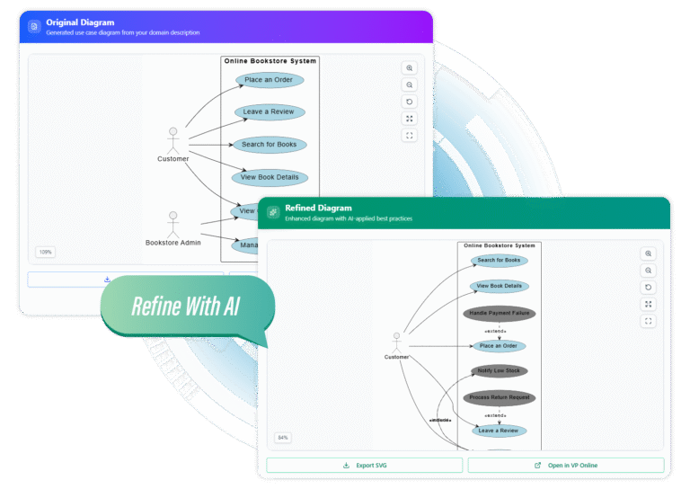
This guide explores how to leverage AI to transform natural language descriptions into professional, accurate Use Case diagrams in seconds. By shifting the focus from drawing to describing, architects and developers can iterate faster and uncover deeper insights into their system requirements.
Key Concepts in AI-Driven Diagramming
Before diving into the workflow, it is essential to understand the core terminologies that AI engines utilize to construct these models. Understanding these concepts ensures you provide the best possible input prompts to the AI.
- Actors: These represent the entities that interact with your system. An actor can be a human user (e.g., “Administrator”) or an external system (e.g., “Payment Gateway”).
- Use Cases: These are the specific functions or goals the system performs for the actor (e.g., “Login,” “Checkout,” “Generate Report”).
- System Boundary: The scope of your system. AI needs to know what is internal to the application and what remains external.
- Relationships: The lines connecting actors to use cases.
- <<include>>: A relationship where one use case explicitly incorporates the behavior of another (mandatory execution).
- <<extend>>: A relationship where a use case might add behavior to another under specific conditions (optional execution).
The 3-Step Workflow: From Text to Visuals
Modern AI diagramming tools streamline the creation process into three intuitive phases. This approach allows for rapid prototyping and eliminates the “blank canvas” paralysis often faced by system designers.
1. Describe Your System
The foundation of a good AI-generated diagram is a clear prompt. You do not need to write code; you simply need to describe the domain. The engine parses natural language to identify actors and their goals. Be specific about stakeholders and the core purpose of the application.
2. Generate the Base Model
With a single click, the AI translates your text into a structured diagram. It automatically places actors, draws the system boundary, and creates associations. This instant visualization provides a live preview, allowing you to catch requirements gaps immediately.
3. Intelligent Refinement
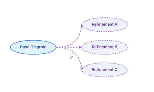
This is where AI transcends simple automation. By clicking “Refine,” the AI analyzes the initial model against UML best practices. It suggests and implements complex relationships like extends and includes, enriching the model. You can cycle through multiple structural suggestions to explore alternative scenarios you might not have considered.

Examples: Natural Language to Structured Output
To illustrate the power of AI generation, let’s look at a before-and-after scenario for a standard banking application.
Scenario: ATM System
Input Description (Natural Language):
“I need a diagram for an ATM system. The main actors are the Customer and the Bank Technician. The Customer should be able to Withdraw Cash, Deposit Checks, and Check Balance. The Bank Technician performs Maintenance and Refills Cash. All transactions require the user to Authenticate first. Sometimes, during a withdrawal, the system needs to Check for Sufficient Funds.”
AI-Generated Output Structure:
| Element Type | Generated Components |
|---|---|
| Actors | Customer, Bank Technician |
| Primary Use Cases | Withdraw Cash, Deposit Checks, Check Balance, Perform Maintenance, Refill Cash |
| Relationships | <<include>>: Connects “Withdraw Cash”, “Deposit Checks”, and “Check Balance” to “Authenticate”. <<extend>>: Connects “Check for Sufficient Funds” to “Withdraw Cash”. |
The AI automatically recognizes that “Authenticate” is a shared prerequisite (Include) and that “Check for Sufficient Funds” is conditional logic (Extend), saving manual configuration time.
Advanced Features for Professional Workflows
While generation is fast, professional documentation requires precision and flexibility. Top-tier AI diagramming tools offer specific features to bridge the gap between a draft and a final deliverable.
- Visual Paradigm Integration: Generated diagrams are not static images. You can open them in editors like Visual Paradigm Online to tweak layout, change colors, or add annotations manually.
- SVG Export: For high-resolution documentation, scalable vector graphics (SVG) are essential. This ensures your diagrams remain crisp in printed reports or large presentations.
- Live Iteration: The ability to re-roll suggestions helps explore the full potential of the system. If the first diagram feels too cluttered, the AI can offer a streamlined alternative version.
Implementation Checklist
Before finalizing your AI-generated use case diagram for stakeholder review, run through this audit checklist to ensure accuracy and compliance with UML standards.
- Actor Verification: Are all primary and secondary stakeholders represented? (e.g., Did the AI catch external APIs as actors?)
- Verb-Noun Naming: Do all use cases start with a strong verb? (e.g., “Process Payment” instead of “Payment”).
- Relationship Logic: verify that <<include>> relationships represent mandatory behavior and <<extend>> relationships represent optional behavior.
- Scope Check: Is the system boundary clearly defined? Ensure no internal system processes are masquerading as external actors.
- Readability: Is the diagram layout clean? Use the “Edit” function to minimize crossing lines if the AI generation resulted in a complex web.
- Export Format: Have you exported in the correct format (SVG/PNG) for your documentation platform?
By following this guide, you can transition from manual drafting to AI-assisted architectural design, ensuring your diagrams are not only beautiful but also structurally sound and standardized.
-
From Problem Description to Class Diagram: AI-Powered Textual Analysis: Explore how Visual Paradigm uses AI to convert natural language problem descriptions into accurate class diagrams for software modeling.
-
How to Translate Text in Images for UML, BPMN, and Flowcharts: Step-by-step guide on using AI-powered tools to extract and translate text in technical diagrams for global collaboration and localization.
-
AI Chatbot Feature – Intelligent Assistance for Visual Paradigm Users: Leverage AI-powered chatbot functionality to get instant guidance, automate tasks, and enhance productivity within Visual Paradigm.
-
Visual Paradigm Chat – AI-Powered Interactive Design Assistant: An interactive AI chat interface that helps users generate diagrams, write code, and solve design challenges in real time.
-
AI Textual Analysis – Transform Text into Visual Models Automatically: Use AI to analyze text documents and automatically generate diagrams such as UML, BPMN, and ERD for faster modeling and documentation.
-
Visual Paradigm AI Chatbot Enhances Multi-Language Support …: 7 hours ago · Discover the latest updates to Visual Paradigm ‘s AI -Powered visual modeling software, including multi-language UI and improved chat content localization. Experience seamless AI diagram generation in languages like Spanish, French, Chinese, and more with our AI chatbot for UML and other diagrams.
-