


Introduction
In the landscape of object-oriented design, the and relationships within UML Use Case diagrams serve as the foundational pillars for modularizing functional requirements, promoting code reuse, and clarifying complex actor-system interactions. Without these constructs, use case diagrams tend to become bloated, difficult-to-maintain monoliths.
These relationships are not merely theoretical UML notations; they are critical engineering tools. When combined with modern modeling tools like Visual Paradigm (VP), these constructs transform from abstract concepts into a streamlined, high-precision workflow. This article explores the purpose of these relationships, their transformative impact on the IT development lifecycle, their pros and cons, best practices for implementation, and specifically how Visual Paradigm leverages AI and automation to amplify their effectiveness.
1. The Core Purpose and Definitions
Understanding the semantics of directionality and flow is the first step toward effective modeling.

The <include> Relationship: Mandatory Reuse
The relationship indicates that the base use case always incorporates the behavior of the included use case as a mandatory subroutine. It extracts reusable, shared steps from other use cases, reducing redundancy.
-
Semantics: The base use case is incomplete without the included behavior.
-
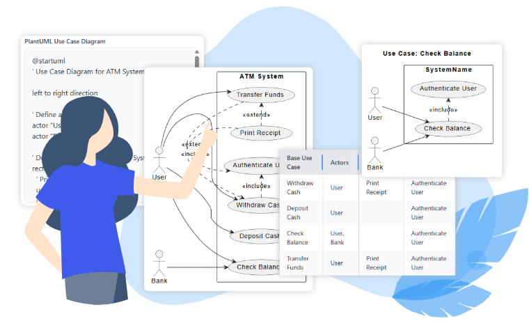
Example: “Withdraw Cash” (Base) always requires “Authenticate User” (Included) before any money can move.
-
Notation: A dashed arrow labeled
<include>points from the base use case to the included use case (Base $\to$ Included). -
Developer Impact: Includes map directly to shared libraries, API calls, or service layers in the system architecture.
The <extend> Relationship: Conditional Augmentation
The relationship signifies that an extending use case conditionally augments the base use case at explicitly defined extension points. The base use case remains fully functional and independent even when the extension does not occur.
-
Semantics: Used for optionals, variants, error paths, or conditional flows (e.g., a special flight during a sale).
-
Example: “Apply Coupon” (Extension) applies to the “Checkout” (Base) only if a valid coupon code is provided.
-
Notation: A dashed arrow labeled
<extend>points from the extending use case to the base use case. Crucially, the base use case must define specific extension points inside its oval. -
Developer Impact: Extensions map to feature toggles, plugins, or specific execution branches that only trigger under guard conditions.
2. Impact on the IT Development Process
The correct application of <include> and <extend> ripples through every phase of the Software Development Life Cycle (SDLC). Visual Paradigm acts as a force multiplier here, converting manual modeling efforts into automated, traceable engineering artifacts.
| Development Phase | Impact of Include/Extend | Visual Paradigm Acceleration |
|---|---|---|
| Requirements & Analysis | Teams identify shared behaviors (include) and variants (extend) early, preventing overlap. | AI Refinement Tool: Analyzes plain-text requirements or raw sketches, intelligently suggesting the correct use of includes/extends based on UML best practices, reducing analysis time by up to 70%. |
| Design & Architecture | Includes map to shared services; extensions become pluggable modules. | Traceability Engine: VP automatically maintains traceability matrices linking use cases to downstream class/sequence diagrams and generated code stubs. |
| Implementation | Reuse via include eliminates code duplication; conditional extend supports plugins. | Flow of Events Editor: Allows analysts to reference included use cases directly in steps, attaching guard conditions and producing machine-readable specifications for developers. |
| Testing & Maintenance | Centralized includes mean one test suite covers multiple flows. | Extend & Include Analyzer: Instantly generates relationship tables and focused sub-diagrams. Ideal for regression testing and impact analysis when requirements evolve. |
3. Pros, Cons, and VP Mitigation Strategies
While powerful, these relationships carry risks if misused. Visual Paradigm addresses common pitfalls through intelligent validation and automation.
✅ Advantages
-
Massive Reuse and Consistency: By separating common logic (includes), teams avoid duplicating the same authentication or logging routines across dozens of use cases.
-
Clean, Extensible Core Flows: The base system remains stable and testable at its core, while optional features (extensions) can be developed separately.
-
Improved Communication: Provides a clear language for stakeholders to understand what happens (include) and when extra steps happen (extend).
⚠️ Challenges & VP Solutions
| Challenge | Risk Description | How Visual Paradigm Mitigates It |
|---|---|---|
| Over-Fragmentation | Misuse leads to excessive depth or tiny, unrelated use cases (“spaghetti”). | AI Refinement & Validation Rules: The tool flags incorrect directions or unnecessary fragmentation, enforcing a cleaner model structure. |
| Complex Navigation | Deep nesting of dependencies can make diagrams unreadable. | Analyze & Simplify Tools: VP’s Extend and Include Use Case Analyzer generates instant relationship summaries and isolated sub-views for quick reference. |
| Documentation Overhead | Manual writing of narratives and tables is time-consuming and error-prone. | Auto-Generation: VP automatically generates use-case narratives, extension-point tables, and full traceability reports. |
| Learning Curve | Distance between manual UML syntax and modern workflow is steep. | Guided Onboarding: Built-in tutorials, templates (ATM, DMS), and an AI Chatbot that guides users through proper workflow steps in real-time. |
4. Best Practices: A Hand-Operated Workflow Enhanced by Visual Paradigm
To master these relationships, one must first understand the logic, then leverage the tool to implement it flawlessly.
Part 1: The Manual Well-Written Rules
-
Identify Reuse: Scan your draft primary use cases for mandatory shared steps (triggers
include) versus conditional ones (triggersextend). -
Respect Directionality: Never flip the arrows. Always ensure the arrow points from the actor/base to the included use, and from the extending use to the base.
-
Define Points Explicitly: For
<extend>, every extension must have a clearly named Extension Point inside the base use case oval. Without this, the link is invalid. -
Limit Nesting: Keep use case depth shallow. If a relationship requires multiple levels of abstraction, document the detailed flow in scenarios rather than creating new layers of use cases.
Part 2: The Visual Paradigm Implementation Workflow
Visual Paradigm transforms these abstract rules into a concrete, error-proof process.
-
Step 1: Create the Base Diagram
Use VP Online or Desktop to drag actors and use cases from the palette. Establish your primary flows without immediate relationships. -
Step 2: Introduce Relationships via Resource Catalog
Hover over any use case and access the Resource Catalog. Select “Include $\to$ Use Case” or “Extend $\to$ Use Case.” VP automatically creates the correct dashed arrow and, forextend, inserts an editable extension point automatically. -
Step 3: Define Extension Points & Flows
Double-click the base use case. Open the Use Case Details window or the specific “Extension Points” compartment. Here, you can write the textual flow, defining the guard conditions (e.g., “If discount > 10%”). -
Step 4: AI-Powered Refinement
Select the diagram and invoke the AI Use Case Diagram Refinement Tool (or AI Chatbot). The engine analyzes your model, detects opportunities to improve structure, suggests missing relationships, and applies UML best practices to regenerate a polished version instantly. -
Step 5: Analyze Complexity
For diagrams with more than 10 use cases, run the Extend and Include Use Case Analyzer (Tools $\to$ Apps). It produces:-
Human-readable relationship tables.
-
Focused sub-diagrams for any selected base use case.
-
Exportable PlantUML code for version control and external collaboration.
-
-
Step 6: Traceability & Documentation
Generate official reports. VP links use cases to test cases, exports influence matrices, and creates Word/PDF outputs with embedded diagrams and extension-point matrices. -
Step 7: Collaborative Iteration
For real-time collaboration, use VP Online. Version history allows stakeholders to see the impact of changes instantly, ensuring alignment before sprint planning.
5. Conclusion
The and relationships are not merely UML formalities; they are the bedrock of scalable systems engineering. They enable the separation of core functionality from optional variations, driving both code reuse and architectural clarity.
However, the theoretical power of these concepts meets its greatest reservoir in practical application. By integrating Visual Paradigm’s specialized features—such as the automated Resource Catalog integration, AI-driven refinement, the Extend & Include analyzer, and centralized traceability—these relationships evolve from abstract theory into a streamlined, low-risk industrial standard.
Organizations that embrace this modern approach consistently report faster stakeholder alignment, a drastic reduction in rework cycles, and clearer handoffs between analysis, development, and testing teams. In an era defined by rapid change and AI-augmented design, leveraging Visual Paradigm turns the classic UML technique into a decisive competitive advantage.
Use Case Diagram Resource
- “Include” and “Extend” Use Cases: A core explanatory article from the Visual Paradigm Blog detailing the definitions, differences, examples (e.g., invalid password scenarios), and when to apply <<include>> (mandatory reuse) versus <<extend>> (optional/conditional insertion) in use case diagrams.
- What is Use Case Diagram?: Official Visual Paradigm guide covering use case basics, with dedicated sections and examples on <<extend>> (optional behavior) and <<include>> (common behavior reuse), including stereotypes, arrow directions, and practical diagram illustrations.
- Use Case Diagram Tutorial: Comprehensive tutorial on Visual Paradigm Online explaining how to structure use cases with <<include>> and <<extend>> after initial identification, complete with step-by-step structuring advice and example diagrams.
- Extend and Include Use Case Analyzer: Feature page describing Visual Paradigm’s specialized tool that analyzes complex diagrams, generates relationship tables, visualizes dependencies, and simplifies understanding of all <<include>> and <<extend>> connections for better architecture insight.
- How to Draw Use Case Diagram?: Step-by-step Visual Paradigm user guide on creating <<extend>> and <<include>> relationships using the Resource Catalog, including precise instructions for dragging arrows, defining extension points, and avoiding common notation errors.
- Structuring Use Cases with Base, Include, and Extend: A Guide for Effective Software Development: In-depth guide from Visual Paradigm on using base, <<include>> (shared functionality), and <<extend>> (optional/conditional) use cases to build clear, maintainable models for software projects.
- Extend vs Include in Use Case Diagrams – UML Explained: AI-focused Visual Paradigm article comparing the two relationships with analogies, arrow direction explanations, and details on how their AI tool automatically refines and corrects <<include>>/<<extend>> in diagrams.
- Include and Extend Use Case Diagram Template: Ready-to-use template page in Visual Paradigm Online with explanations of <<include>> (mandatory incorporation) and <<extend>> (conditional addition with guards), plus references and example usage.
- Website (Structuring Use Cases with Extend and Include Use Case): Community Circle example from Visual Paradigm demonstrating real-world structuring with <<include>> for common sequences and <<extend>> for alternate courses in a website context.
- Why Focus on a Specific Use Case with Include and Extend Relationships? (Extend and Include Use Case Analyzer): AI-enhanced article explaining the value of focusing on individual use cases via Visual Paradigm’s Analyzer tool, with PlantUML integration for quick relationship breakdowns and dependency visualization.