В постоянно меняющейся среде инженерии программного обеспечения умение визуализировать архитектуру системы имеет первостепенное значение.Единый язык моделированияДиаграммы классов (UML) остаются определяющим стандартом объектно-ориентированного проектирования, выступая в качестве чертежа сложных программных систем. Однако традиционные методы ручного построения этих диаграмм быстро трансформируются с помощью искусственного интеллекта.
Это всеобъемлющее руководство исследует основные концепции диаграмм классов UML, отличает их от диаграмм объектов и глубоко погружается в то, какVisual Paradigm революционизирует отрасль с помощью моделирования на основе искусственного интеллекта, анализа текста и передовых возможностей двухсторонней инженерии.
Понимание диаграмм классов UML: Основные концепции
В основе своей диаграмма UMLдиаграмма классовфиксирует статическую структуру системы. В отличие отдинамических диаграммкоторые иллюстрируют поведение во времени (например,последовательностиилидиаграмм деятельности), диаграммы классов предоставляют структурную карту. Они определяют типы объектов в системе и различные статические отношения между ними.
Чтобы создать эффективную модель, необходимо понимать основные строительные блоки:
1. Классы
Класс представляет собой чертеж для объектов. Он инкапсулирует данные и поведение, относящиеся к конкретной сущности в системе. ВUML, класс обычно изображается в виде прямоугольника, разделенного на три секции:
- Имя класса: Идентификатор класса (например,Клиент, Заказ).
- Атрибуты: Свойства данных или состояние, которое хранит класс.
- Операции/Методы: Поведенческие функции или услуги, которые предоставляет класс.
2. Индикаторы видимости
Определение контроля доступа имеет решающее значение для инкапсуляции. UML использует специфические символы для обозначения видимости:
| Символ | Тип видимости | Описание |
|---|---|---|
| + | Публичный | Доступен из любого другого класса. |
| – | Приватный | Доступен только внутри самого класса. |
| # | Защищенный | Доступен в классе и его подклассах. |
| ~ | Пакет/По умолчанию | Доступен только классами в том же пакете. |
3. Связи
Классы редко существуют изолированно. Сила диаграммы классов заключается в связях, которые определяют, как классы взаимодействуют. Visual Paradigm поддерживает точное моделирование этих связей:
- Ассоциация: Общая связь, при которой классы связаны между собой (например, учитель учит ученика).
- Агрегация: Связь «имеет-а», представляющая иерархию целого/части, при которой часть может существовать независимо от целого (например, библиотека имеет книги, но книги могут существовать без конкретной библиотеки).
- Композиция: Сильная связь «часть-целое», при которой жизненный цикл дочернего объекта зависит от родительского (например, дом и его комнаты).
- Наследование (обобщение): Связь «является-а», указывающая, что подкласс наследует структуру и поведение от суперкласса.
- Зависимость: Связь, при которой изменение одного класса (поставщика) может повлиять на другой класс (клиента).
Диаграммы классов против диаграмм объектов: ключевые различия
Хотя часто обсуждаются вместе, диаграммы классов и диаграммы объектов выполняют разные функции в жизненном цикле моделирования. Понимание различий имеет решающее значение для точного представления системы.
| Функция | Диаграмма классов | Диаграмма объектов |
|---|---|---|
| Уровень абстракции | Высокоуровневый шаблон | Конкретный экземпляр |
| Область применения | Абстрактные правила, определения и структура. | Снимок экземпляров во время выполнения в определенный момент времени. |
| Цель | Моделирование домена и проектирование архитектуры программного обеспечения. | Проверка конкретных сценариев или отладка логических состояний. |
| Временной параметр | Статический (независимый от времени). | Снимок (конкретный момент времени). |
Visual Paradigm позволяет пользователям моделировать оба, обеспечивая, что абстрактные правила, определенные вдиаграммах классовмогут быть проверены на основе конкретных сценариев объектов для проверки логики до написания первой строки кода.
Революция искусственного интеллекта: моделирование в Visual Paradigm
Ручное создание диаграмм может быть утомительным и подвержено человеческим ошибкам. Visual Paradigm интегрировал передовые технологии искусственного интеллекта, чтобы сместить акцент с «рисования» на «моделирование». Используя современные возможности ИИ, платформа ускоряет процесс создания, часто сокращая часы работы до нескольких секунд или минут.
Анализ текста с использованием искусственного интеллекта
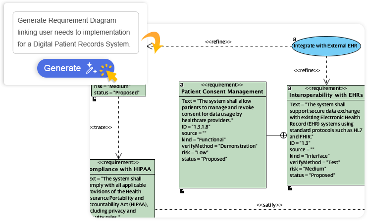
Одной из самых сложных фаз разработки программного обеспечения является преобразование неструктурированных требований в структурированный дизайн.Анализ текста с использованием искусственного интеллекта от Visual Paradigm инструмент напрямую решает эту задачу.
Пользователи могут вводить текст на естественном языке — например, формулировку проблемы, пользовательскую историю или документ с требованиями. Модуль ИИ анализирует этот текст для автоматического извлечения:
- Кандидатские классы
- Атрибуты и типы
- Операции/Методы
- Связи между сущностями
После извлечения инструмент направляет пользователя через процесс уточнения, чтобы обеспечитьUMLСоответствие версии 2.5. Это создает полную, редактируемую диаграмму классов непосредственно из текста требований, устраняя разрыв между бизнес-аналитиками и архитекторами систем.
Конверсационный ИИ (интеграция чат-бота)
Для интерактивного опыта моделирования Visual Paradigm предлагаетЧат-бот ИИ(доступен через chat.visual-paradigm.com или встроенный). Эта функция позволяет разработчикам создавать диаграммы через диалог.
Например, пользователь может ввести:«Создать диаграмму классов UML для онлайн-библиотечной системы, включающей Book, Member, Loan и связи.»
ИИ мгновенно интерпретирует контекст и создает профессиональную диаграмму с:
- Чистые, автоматически упорядоченные макеты.
- Правильные стандартные обозначения.
- Советы, учитывающие контекст, для улучшения.
Этот итеративный процесс позволяет пользователям естественным образом уточнять модель (например,«Добавить атрибут для ISBN в класс Book»), что делает его чрезвычайно эффективным для быстрого прототипирования.
Генератор диаграмм классов с поддержкой ИИ
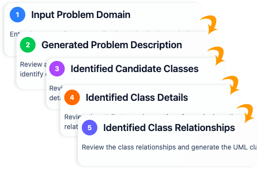
Для комплексных настроек проектовМастер с поддержкой ИИпредлагает структурированный процесс из 10 шагов. Этот инструмент сочетает простые вводы пользователей с глубоким анализом ИИ для:
- Определить масштаб системы.
- Заполнить структурные пробелы.
- Предложить логические связи на основе знаний в области предметной области.
- Проверить целостность структуры.
- Создать отчеты по анализу архитектуры.
Этот инструмент особенно мощен при экспорте моделей в различные форматы, включая PlantUML, SVG и JSON, обеспечивая совместимость с другими инструментами в стеке разработки.
Связь между проектированием и кодом: Расширенные инженерные возможности
Диаграмма полезна только в той мере, в какой она реализована.Visual Paradigmпревосходно справляется с мостом между теоретическим проектированием и исполняемым кодом, поддерживая разработку на протяжении всего жизненного цикла.
1. Генерация исходного кода
Как только диаграмма классов будет завершена, Visual Paradigm может автоматически генерировать готовый к использованию исходный код. Он поддерживает основные языки программирования, такие какJava, C#, иC++. Это гарантирует, что структуры классов, иерархии наследования и сигнатуры методов в коде точно соответствуют проекту, экономя разработчикам время на ручной написании шаблонного кода.
2. Интеграция ORM
Для приложений, требующих постоянного хранения данных, платформа обеспечиваетобъектно-реляционное отображение (ORM). Он может генерировать код, соответствующий Hibernate или JPA, эффективно отображая объектно-ориентированную модель на реляционные схемы баз данных. Эта автоматизация значительно снижает сложность слоя доступа к данным.
3. Инженерия двунаправленного обмена
Возможно, наиболее важной особенностью для поддержки долгосрочных проектов являетсяинженерия двунаправленного обмена. Программное обеспечение развивается, и часто изменения кода происходят быстрее, чем обновления документации.
Visual Paradigm решает эту проблему с помощью двунаправленной синхронизации:
- Прямое проектирование: Редактируйте диаграмму для обновления исходного кода.
- Обратное проектирование: Внесите изменения в исходный код и синхронизируйте их обратно с моделью.
Это гарантирует, что документация (модель) никогда не устареет, обеспечивая единый источник истины на протяжении всего жизненного цикла приложения.
Заключение
Visual Paradigmвыделяется какплатформа «всё в одном»которая гармонично сочетает традиционныеUML преимущества с передовыми средствами автоматизации на основе искусственного интеллекта. Независимо от того, определяете ли вы модель домена, проверяете сценарий выполнения с помощью диаграмм объектов или генерируете код Hibernate для сложной корпоративной системы, интеграция инструментов искусственного интеллекта — от анализа текста до чат-бота — гарантирует, что моделирование осуществляется быстрее, умнее и соответствует стандартам.
Для разработчиков, архитекторов и команд, стремящихся сократить время проектирования при сохранении высокого качества инженерных результатов, использование этих возможностей на основе искусственного интеллекта больше не является роскошью, а является необходимостью в конкурентной борьбе.
-
Генератор диаграмм классов UML с поддержкой искусственного интеллекта – Visual Paradigm: Этот инструмент позволяет пользователям генерировать диаграммы классов UML с рекомендациями на основе искусственного интеллекта, проверкой, экспортом в PlantUML и анализом дизайна.
-
Генератор диаграмм классов UML на основе искусственного интеллекта от Visual Paradigm: Пользователи могут генерировать точные диаграммы классов UML на основе описаний на естественном языке с помощью автоматизации с поддержкой искусственного интеллекта.
-
Интерактивный чат на основе искусственного интеллекта для генерации диаграмм классов UML: Этот интерфейс диалогового искусственного интеллекта позволяет генерировать диаграммы классов UML с помощью взаимодействия на естественном языке непосредственно в веб-браузере.
-
Генератор диаграмм классов UML с поддержкой искусственного интеллекта – AI Toolbox от Visual Paradigm: Этот инструмент на основе искусственного интеллекта генерирует диаграммы классов UML на основе текстовых описаний, требуя минимального ручного ввода.
-
От описания проблемы к диаграмме классов: анализ текста на основе искусственного интеллекта: Анализ текста на основе искусственного интеллекта от Visual Paradigm преобразует описания проблем на естественном языке в точные диаграммы классов.
-
Определение классов домена с помощью анализа текста на основе искусственного интеллекта в Visual Paradigm: Инструменты искусственного интеллекта в Visual Paradigm автоматически определяют классы домена на основе неструктурированного текста, упрощая процесс моделирования программного обеспечения.
-
Как искусственный интеллект улучшает создание диаграмм классов в Visual Paradigm: Искусственный интеллект автоматизирует проектирование и повышает точность создания диаграмм классов при минимальном вводе пользователя.
-
Упрощение диаграмм классов с помощью искусственного интеллекта от Visual Paradigm: Инструменты искусственного интеллекта в платформе сокращают время и сложность, необходимые для создания точных диаграмм классов для проектов программного обеспечения.
-
Практический пример: создание диаграмм классов UML с помощью искусственного интеллекта от Visual Paradigm: Этот практический пример демонстрирует, как помощник на основе искусственного интеллекта успешно преобразует текстовые требования в точные диаграммы классов UML для реальных проектов.