


Designing a robust software architecture begins with clarity. When the blueprint of your system is ambiguous, the resulting code often suffers from tight coupling, maintenance nightmares, and logical inconsistencies. A class diagram is not merely a drawing exercise; it is a communication tool that defines how objects interact, inherit, and depend on one another. Yet, many developers find themselves staring at a diagram where relationships seem to contradict the actual implementation.
This guide addresses the most common structural failures in UML class modeling. We will move beyond surface-level aesthetics to examine the logic, cardinality, and semantic meaning behind every line and arrow. By identifying these patterns early, you ensure that your design remains scalable and maintainable throughout the development lifecycle.
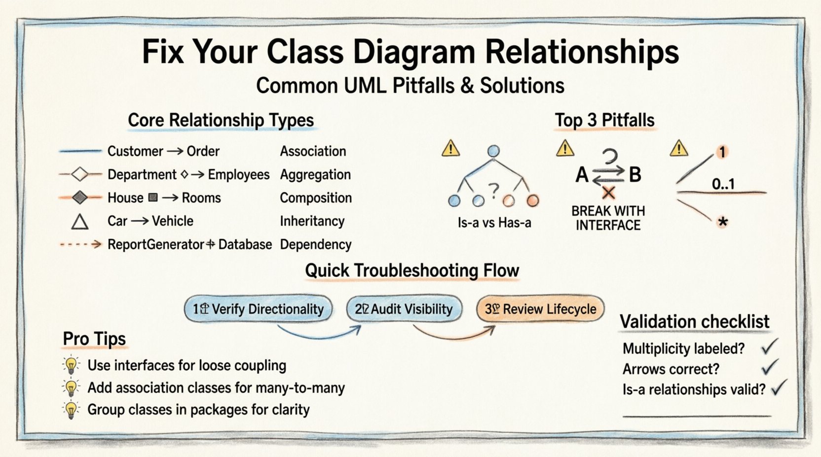
🧩 Understanding the Core Relationship Types
Before troubleshooting, one must understand the standard vocabulary of class relationships. Confusion often arises when terms are used interchangeably or when the visual notation does not match the intended semantics. Below is a breakdown of the primary relationship types you will encounter.
| Relationship Type | Notation | Semantic Meaning | Typical Use Case |
|---|---|---|---|
| Association | Line | Structural connection between two classes. | Customer orders an Order. |
| Aggregation | Hollow Diamond | Whole-part relationship where parts exist independently. | A Department has Employees (Employees leave the department). |
| Composition | Filled Diamond | Strong whole-part relationship; parts do not survive without the whole. | A House has Rooms (Rooms cease to exist if the house is demolished). |
| Inheritance | Line with Hollow Triangle | “Is-a” relationship. Parent provides common structure. | Car is a Vehicle. |
| Dependency | Dashed Line with Arrow | Usage relationship. One class uses another temporarily. | ReportGenerator uses a DatabaseConnection. |
🔍 Common Pitfalls in Relationship Modeling
When a diagram fails, it usually stems from a disconnect between the visual representation and the logical reality of the system. Below are the specific scenarios where relationships break down.
1. Inheritance vs. Composition Confusion
This is perhaps the most frequent error in object-oriented design. Developers often default to inheritance when they should be using composition, or vice versa. This choice dictates the lifecycle management and coupling depth of your classes.
- The Symptom: You have a
WingedLionclass that inherits fromAnimalandMachine. This creates a diamond inheritance problem or a logical contradiction (is a lion a machine?). - The Impact: Tight coupling to the parent class, fragility in refactoring, and violation of the Liskov Substitution Principle.
- The Fix: Ask yourself: “Is this an is-a relationship?” If a
Caris not strictly aVehiclein every context, consider composition. If aCarhas anEngine, the engine is a part, not a parent class. Use composition for “has-a” relationships.
2. Circular Dependencies
Dependencies should flow in one direction. When Class A depends on Class B, and Class B depends on Class A, you create a circular reference. This often leads to initialization errors or the need for complex dependency injection patterns just to resolve the bootstrapping process.
- The Symptom: A loop in your dependency graph. You cannot instantiate A without B, and you cannot instantiate B without A.
- The Impact: Reduced modularity, difficulty in testing individual units, and potential stack overflow errors during object creation.
- The Fix: Extract the common logic into a third, independent class (Interface or Abstract Base). Both A and B should depend on this new abstraction, breaking the direct link between them. Alternatively, introduce an intermediary service that manages the interaction.
3. Ambiguous Multiplicity
Multiplicity defines how many instances of one class relate to one instance of another. Missing this detail renders the diagram useless for implementation.
- The Symptom: A relationship line exists, but no numbers are present (e.g.,
1,0..1,*). - The Impact: Developers make assumptions. One might use a single reference, while another implements a list. This leads to data inconsistencies.
- The Fix: Explicitly define the cardinality. Use
1for exactly one,0..1for optional, and*or0..*for many. Ensure both ends of the association are labeled correctly.
🔧 Step-by-Step Troubleshooting Workflow
When your diagram does not match your code, or when the design feels “off,” follow this structured approach to identify and resolve the issues.
Step 1: Verify Directionality
Arrows indicate the direction of dependency. If you have a relationship between User and Profile, who knows about whom?
- Does the
Userobject hold a reference to theProfile? - Does the
Profileobject hold a reference back to theUser?
If both are true, you need a bidirectional association. If only one is true, ensure the arrow points from the dependent class to the known class. Often, diagrams show arrows pointing both ways without justification, creating visual clutter.
Step 2: Audit Visibility Modifiers
While visibility (public, private, protected) is often omitted in high-level diagrams, it is critical for troubleshooting implementation failures. If a relationship implies interaction, the attribute must be accessible.
- Check if the relationship implies a method call. Is that method
public? - Check if the relationship implies field access. Is that field
private?
If the diagram suggests direct access to a private field, the design is flawed. Refactor to use getters or interface methods.
Step 3: Review Lifecycle Constraints
Aggregation and Composition are often confused because both look like “part-of” relationships. The difference lies in lifecycle management.
- Composition: If the parent is destroyed, the child is destroyed. (Filled diamond).
- Aggregation: The child can exist independently. (Hollow diamond).
If your diagram shows a filled diamond but the code allows the child object to be shared across multiple parents, you are modeling Composition incorrectly. This leads to memory leaks or unexpected data loss.
📉 Deep Dive: Association and Cardinality
Associations are the backbone of class diagrams. They define the structural links. Troubleshooting associations requires a focus on the constraints placed on the data.
Many-to-Many Relationships
Directly modeling a many-to-many relationship (e.g., Students and Courses) in a relational database or object graph often requires an intermediate class. In a class diagram, this might look like a direct line with * on both ends. However, in implementation, this often necessitates a linking entity.
- The Issue: You cannot store metadata about the relationship (e.g., the date a student enrolled in a course) on the line itself.
- The Solution: Introduce an association class. Create a new class (e.g.,
Enrollment) that connectsStudentandCourse. This class holds the specific attributes of the relationship.
Optional vs. Mandatory Links
Confusion between mandatory (1) and optional (0..1) relationships leads to validation errors.
- Scenario: A
BankAccountis linked to aCustomer. - Question: Can a customer exist without an account?
- Design: If yes, the link from Customer to Account is
0..1. If no, it is1.
Incorrectly marking a mandatory link as optional allows null values where business logic requires data. Incorrectly marking an optional link as mandatory forces data entry that might not be available.
🔄 Dependency Management
Dependencies are the most volatile relationships. They represent usage, not ownership. A class A depends on Class B if a change in B might require a change in A.
The Dependency Inversion Principle
High-level modules should not depend on low-level modules. Both should depend on abstractions. When troubleshooting, look for direct instantiation of concrete classes within dependencies.
- Bad Pattern:
ReportGeneratorinstantiatesMySQLConnectiondirectly. - Good Pattern:
ReportGeneratordepends on an interfaceDatabaseConnection.
If your diagram shows a dashed line from a high-level class to a specific implementation class, consider refactoring to an interface. This reduces the coupling and makes the diagram more flexible to changes in the underlying technology.
Transitive Dependencies
A common mistake is drawing lines for indirect relationships. If Class A uses Class B, and Class B uses Class C, you do not need to draw a line from A to C.
- Rule: Only draw direct dependencies.
- Reason: Transitive dependencies clutter the diagram and obscure the actual boundary of responsibility. They imply a direct knowledge of C by A, which is not the case.
🎨 Visual Clarity and Maintenance
A diagram that cannot be read is as good as no diagram. When troubleshooting, consider the visual layout as a debugging tool.
Crossing Lines
When relationship lines cross each other without a junction point, it implies no relationship exists. However, this creates visual noise.
- Strategy: Use the “orthogonal routing” style (lines that move only horizontally and vertically) to minimize crossings.
- Strategy: If lines must cross, ensure they are clearly distinct from actual intersection points (which usually imply a ternary relationship or navigation path).
Grouping and Packages
As the system grows, a single diagram becomes overwhelming. Troubleshooting becomes impossible if you cannot locate a specific class.
- Use Packages: Group related classes into logical packages (e.g.,
Domain,Service,Infrastructure). - Use Sub-diagrams: Do not show every detail in one view. Create a high-level overview diagram and drill down into specific subsystems for detailed relationships.
🛠 Refactoring Strategies
Once you have identified the failures, you must apply fixes that align with the diagram. Here are standard patterns for resolving structural issues.
Extracting Interfaces
If a class is too tightly coupled to its implementation, extract an interface. Update the diagram to show the dependency on the interface rather than the concrete class. This clarifies the contract rather than the implementation.
Introducing Facades
If a class has too many dependencies, it is a “God Class.” Introduce a facade class that simplifies the interface. Update the diagram to show the facade as the primary client of the complex subsystem, hiding the internal complexity.
Splitting Responsibilities
If a class is responsible for too many relationships, it violates the Single Responsibility Principle. Split the class into two or more. Update the diagram to show the new classes and redistribute the relationships. This often naturally resolves circular dependency issues.
📝 Checklist for Diagram Validation
Before finalizing your model, run this validation checklist to catch common errors.
- □ Are all relationship lines labeled with their multiplicity?
- □ Do arrows point in the correct direction of dependency?
- □ Are inheritance hierarchies strictly “is-a” relationships?
- □ Are composition relationships strictly “life-cycle dependent”?
- □ Are there any circular dependencies between concrete classes?
- □ Is the diagram readable without excessive line crossing?
- □ Do the visibility modifiers in the code match the implied access in the diagram?
🚀 Moving Forward
A well-structured class diagram acts as a contract between design and implementation. By rigorously troubleshooting relationships, you prevent architectural debt from accumulating. The effort spent correcting association types, cardinality, and dependency direction pays dividends in code stability and team communication.
Remember that diagrams are living documents. As the system evolves, the diagram must evolve with it. Regular reviews of the diagram against the codebase ensure that the blueprint remains accurate. When you encounter a relationship that feels wrong, pause and question the semantic meaning. Does it represent ownership? Usage? Inheritance? Answering these questions correctly is the key to a resilient system.