


UML Interaction Overview Diagrams (IO Diagrams) serve as a critical bridge between high-level activity flows and detailed sequence interactions. They provide a structural overview of control flow between interaction occurrences, allowing architects to visualize complex system behaviors without getting lost in the minutiae of individual message exchanges. However, the nuance of this diagram type often leads to significant modeling errors.
When constructing these diagrams, precision is paramount. A single misplaced control node or a mislabeled frame can alter the semantic meaning of the entire system logic. This guide examines the frequent pitfalls encountered during the creation of Interaction Overview Diagrams and provides authoritative corrections to ensure your models remain accurate and maintainable.
🧩 Understanding the Interaction Overview Diagram
An Interaction Overview Diagram is essentially a hybrid. It combines the control flow logic of an Activity Diagram with the structural containment of an Interaction Diagram. The primary purpose is to show how different interactions are orchestrated over time.
- Nodes: Like activity diagrams, they utilize initial nodes, final nodes, and decision nodes to manage flow.
- Frames: Interaction occurrences are represented using frames, typically referencing Sequence Diagrams or Communication Diagrams.
- Edges: Control flow edges connect these frames, indicating the order of execution.
Because it sits between two other major diagram types, it is prone to misinterpretation. Many modelers apply the rules of one diagram type to the other, resulting in logical inconsistencies.
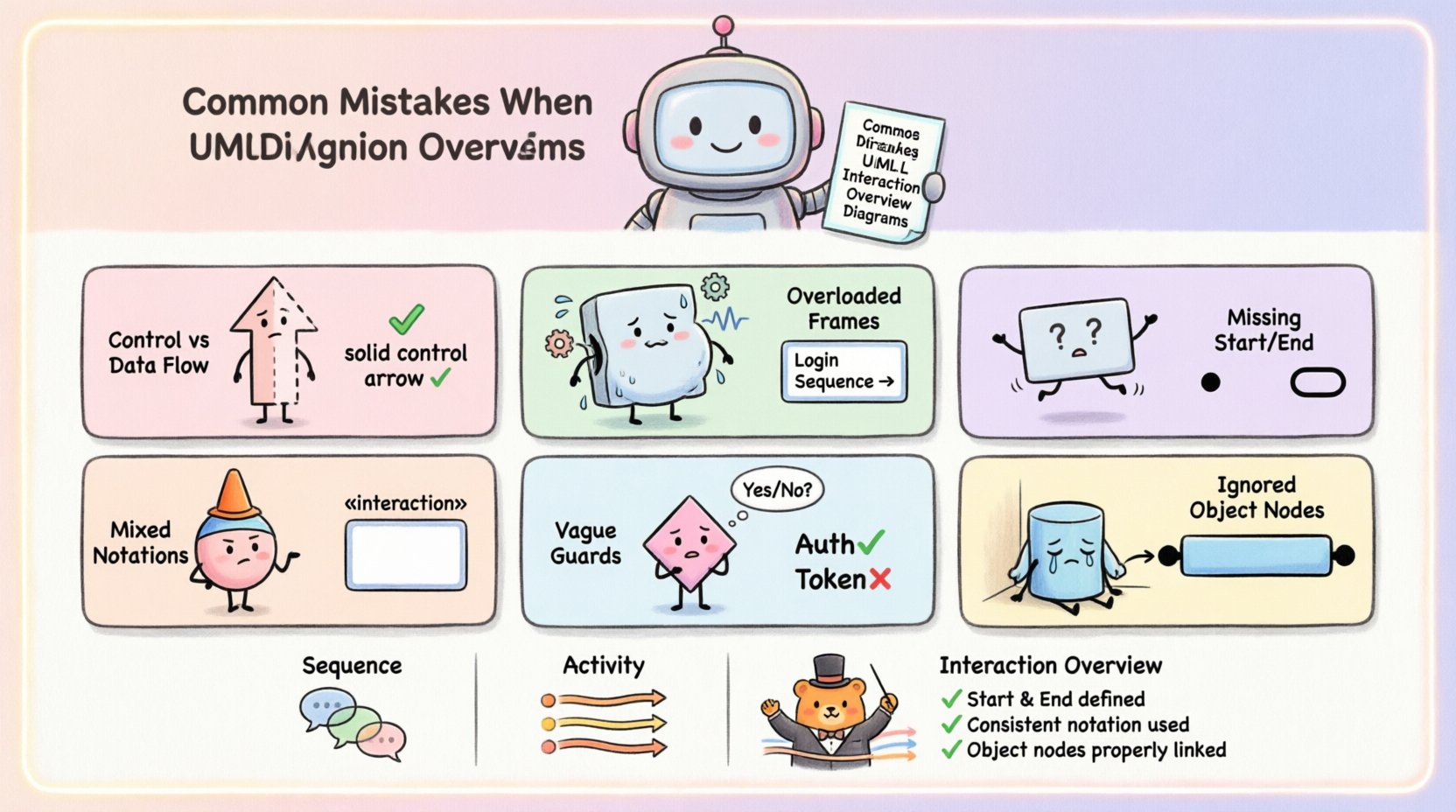
🚫 Common Mistakes and Technical Corrections
Below is a detailed breakdown of the most prevalent errors found in UML Interaction Overview modeling.
1. Confusing Control Flow with Data Flow
The most fundamental error involves the type of edge used to connect interaction frames. In an Activity Diagram, data flows through object nodes, while control flows through control nodes. An Interaction Overview Diagram primarily manages control flow.
- The Mistake: Using data edges or object nodes to dictate the sequence of interactions. For example, connecting two interaction frames via an object node to show that data passed from one triggers the next.
- The Consequence: This violates the UML specification for Interaction Overviews. The diagram becomes a mix of activity and interaction semantics, making it difficult for developers to understand the execution order.
- The Correction: Use standard control flow edges (solid arrows with filled arrowheads) to connect frames. Only use object nodes if you are explicitly modeling data passing within an interaction context, but keep the orchestration logic on control edges.
2. Overloading Interaction Frames
Frames in an Interaction Overview Diagram are meant to encapsulate a specific interaction scenario, typically referencing a separate Sequence Diagram. However, modelers often try to cram too much logic into a single frame.
- The Mistake: Drawing detailed message exchanges, lifelines, and nested logic directly inside the Interaction Overview frame.
- The Consequence: The diagram loses its purpose as an overview. It becomes cluttered and unreadable, defeating the goal of abstraction.
- The Correction: Keep the frame label generic (e.g., "User Login Sequence"). If the logic inside is complex, create a dedicated Sequence Diagram and reference it in the IO Diagram. The IO Diagram should only show the entry and exit points of that interaction.
3. Ignoring Initial and Final Nodes
Every valid interaction overview must have a clear start and a clear end. Omitting these nodes creates ambiguity regarding how the process begins and terminates.
- The Mistake: Starting a control flow edge from nowhere or having a frame dangle without a termination condition.
- The Consequence: The flow is undefined. It is unclear what triggers the first interaction or when the system state is considered complete.
- The Correction: Always place a black filled circle as the initial node. Ensure all paths lead to a final node (a circle with a thick border). If a path ends in a loop, ensure the loop has a defined exit condition leading to the final node.
4. Mixing Notations (Activity vs. Interaction)
This is a semantic clash. The Interaction Overview uses Activity Diagram syntax for flow but Interaction Diagram syntax for the content. Mixing the two incorrectly confuses the reader.
- The Mistake: Using swimlanes (partitioned regions) without proper context, or using Activity Diagram action states instead of Interaction Occurrences.
- The Consequence: Readers may mistake the diagram for a pure Activity Diagram, expecting to see atomic actions rather than system interactions.
- The Correction: Stick to the standard Interaction Overview notation. Use frames with the "Interaction" stereotype. If you need to show partitioning (e.g., by system component), use the Interaction Fragment notation correctly within the frames, not as the primary flow structure.
5. Inconsistent Labeling of Control Edges
nDecision nodes in an Interaction Overview require guards to determine which path is taken. Missing or vague guards render the decision nodes useless.
- The Mistake: Labeling edges from decision nodes with generic terms like "Yes", "No", or leaving them blank.
- The Consequence: The logic is opaque. A developer cannot determine the specific condition required to traverse that path.
- The Correction: Use Boolean expressions or specific state conditions on every edge leaving a decision node (e.g., "Auth Successful", "Token Invalid", "Retry Count < 3"). This provides executable logic clarity.
6. Ignoring Object Nodes within Control Flow
While control flow is primary, Interaction Overview Diagrams can include object nodes to represent state changes that affect flow.
- The Mistake: Treating all nodes as control nodes when they actually represent data objects that influence the next interaction.
- The Consequence: Loss of state information. The diagram fails to communicate that a specific object state is required to proceed.
- The Correction: If an object state determines the flow, explicitly model the object node. Connect the control flow to the object node, then from the object node to the next interaction frame, ensuring the relationship is clear.
📊 Comparison: Interaction Overview vs. Sequence vs. Activity
To avoid confusion, it is helpful to understand where the Interaction Overview fits in the hierarchy of UML diagrams.
| Diagram Type | Primary Focus | Best Used For | Typical Mistake |
|---|---|---|---|
| Sequence Diagram | Message exchange order | Specific interaction details | Showing too many scenarios in one diagram |
| Activity Diagram | Control and data flow | Business process logic | Overusing swimlanes for interaction details |
| Interaction Overview | Orchestration of interactions | High-level flow between sequences | Mixing control flow with data flow logic |
🛡️ Best Practices for Validation
Before finalizing your Interaction Overview Diagram, run through this validation checklist. This ensures the model adheres to UML standards and remains useful for stakeholders.
- Verify Frame References: Do all interaction frames reference valid, existing Sequence Diagrams? If a frame references nothing, the flow is broken.
- Check Loop Bounds: If a loop is present, is the iteration count or condition explicitly defined? Avoid infinite loops without exit strategies.
- Review Decision Guards: Are all paths from a decision node mutually exclusive and collectively exhaustive? (e.g., If one path is "True", the other should be "False").
- Consistency Check: Does the terminology match the Domain Model? Ensure object names in the diagram match the class names in the Class Diagram.
- Flow Completeness: Can every path eventually reach a final node? Dead ends indicate missing logic.
🔄 Handling Nested Interactions
Complex systems often require nested interactions. This means an interaction frame might contain another interaction overview or sequence diagram.
- The Mistake: Creating deep nesting without clear boundaries. This makes tracing the flow difficult.
- The Correction: Limit nesting to two levels maximum. If you need deeper logic, create a separate top-level diagram and reference it. Use clear labeling for nested frames, such as "Nested: Payment Processing".
- Visual Clarity: Ensure the visual hierarchy is maintained. Outer frames should be larger or clearly distinct from inner frames to prevent confusion.
📝 Detailed Mistake Analysis Table
The following table summarizes the critical errors and their technical implications.
| Mistake Category | Technical Symptom | Impact on System Design | Corrective Action |
|---|---|---|---|
| Data vs. Control | Object nodes used for sequencing | Confusion on execution triggers | Switch to Control Flow Edges |
| Frame Content | Details inside the frame | Diagram becomes unreadable | Reference external Sequence Diagram |
| Termination | Missing Final Nodes | Unclear system end states | Add explicit Final Nodes |
| Logic Guards | Blank decision edges | Logic cannot be implemented | Add Boolean Expressions |
| Notation Mixing | Activity states in IO Diagram | Semantic inconsistency | Use Interaction Occurrences |
🧠 Advanced Considerations for Scalability
As systems grow, Interaction Overview Diagrams can become unwieldy. Scaling these models requires strategic planning.
Modularization
Break down complex flows into modules. Instead of one massive diagram covering the entire application lifecycle, create specific diagrams for "Authentication Flow," "Order Processing," and "Reporting." Link them using references where necessary.
State Consistency
Ensure that the state of objects entering an interaction matches the state expected by that interaction. If an interaction requires a "Logged In" state, the control flow leading to it must explicitly show the transition to that state.
Versioning
Interaction Overviews often evolve as requirements change. Maintain version control for the diagram artifacts. When updating a flow, ensure that all references to that interaction are updated simultaneously to prevent broken links in the model.
🔍 Reviewing Your Model
After constructing the diagram, step back and review it from the perspective of a developer implementing the logic.
- Can I code this? If the diagram contains abstract concepts that cannot be translated into code logic, refine the notation.
- Is the path unique? Trace every possible path from start to finish. Are there any ambiguities where two paths look identical but imply different outcomes?
- Are the frames decoupled? The interactions inside the frames should ideally be self-contained. If an interaction frame relies heavily on external context not shown in the diagram, add that context to the IO Diagram.
📉 The Cost of Poor Modeling
Skipping these best practices has tangible costs. A poorly defined Interaction Overview leads to:
- Development Rework: Developers make assumptions about logic that turn out to be incorrect.
- Testing Gaps: Testers may miss edge cases because the decision logic was not clearly defined.
- Communication Breakdown: Stakeholders and engineers will have different mental models of the system flow.
Investing time in correcting these common mistakes upfront saves significant resources during the implementation phase. Precision in the diagram translates directly to precision in the software.
🎯 Final Thoughts on Diagram Integrity
Maintaining the integrity of an Interaction Overview Diagram requires discipline. It is easy to drift into Activity Diagram territory or Sequence Diagram territory. By adhering to the specific syntax and semantics of the Interaction Overview, you ensure that the model serves its intended purpose: orchestrating complex interactions clearly.
Remember the core principles: control flow drives the sequence, frames encapsulate details, and every path must terminate. Apply these rules consistently, and your UML models will remain robust, readable, and valuable assets for your development lifecycle.