


The landscape of software development is shifting rapidly. Requirements engineering, once a static phase of gathering needs, is now a continuous, dynamic process integrated throughout the lifecycle. At the heart of this transformation lies the UML Interaction Overview Diagram (IOD). While often overshadowed by Sequence or Activity diagrams, the IOD is gaining significant traction as a critical tool for mapping complex system behaviors. This guide explores the trajectory of these diagrams, examining how they adapt to modern methodologies and what this means for engineers today. 🔍
Understanding the Interaction Overview Diagram 🧩
Before discussing the future, we must ground ourselves in the present definition. An Interaction Overview Diagram is a structured activity diagram that controls the flow of interactions between objects. It combines the structural aspects of an activity diagram with the behavioral depth of interaction diagrams like Sequence or Communication diagrams.
- Control Flow: It dictates the order in which interactions occur.
- Object Lifelines: It references specific interactions defined elsewhere.
- Decision Points: It handles branching logic based on conditions.
This hybrid nature makes it uniquely suited for high-level requirements modeling. It allows stakeholders to see the “big picture” of a system’s logic without getting bogged down in the minutiae of every single message exchange. 📉
The Traditional Role: Waterfall and Linear Processes 📜
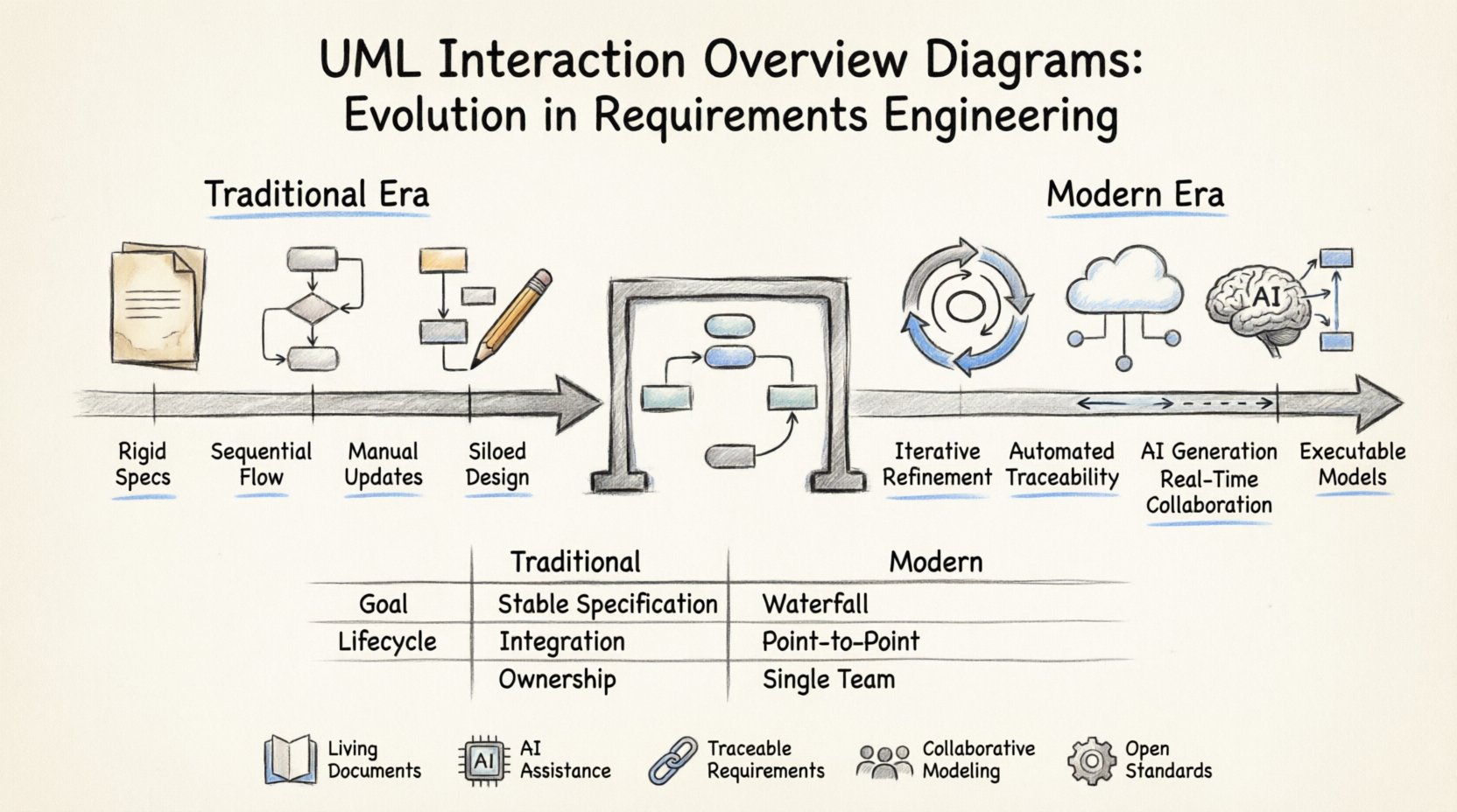
In traditional development models, requirements were captured upfront. The IOD served as a blueprint for developers to follow strictly. Its primary function was documentation and specification. If a requirement changed, the diagram needed to be updated manually, often creating a disconnect between the design and the code.
Key characteristics of the traditional approach included:
- Rigid Specifications: Diagrams were treated as final contracts.
- Sequential Flow: Linear progression through system states.
- Manual Maintenance: Updates were labor-intensive and prone to human error.
- Isolated Views: Diagrams often existed in silos, disconnected from the codebase.
While effective for stable environments, this approach struggled with the volatility of modern software demands. 🛑
Modern Shifts: Agile and DevOps Integration 🔄
The rise of Agile and DevOps has fundamentally altered how requirements are managed. Iterative development means requirements evolve. The IOD must evolve with them. Modern usage focuses on flexibility and traceability rather than rigid specification.
1. Iterative Refinement
Diagrams are no longer “done” artifacts. They are living documents that are refined with every sprint. This allows teams to visualize changes in logic quickly without rewriting entire specifications. The focus shifts from perfect documentation to effective communication.
2. Traceability
Linking diagram elements directly to user stories or requirement IDs is now standard. This ensures that every logical branch in the diagram can be traced back to a specific business need. It validates that the model reflects reality, not just theoretical design.
3. Automated Consistency Checks
Tools now validate that the IOD remains consistent with the rest of the model. If a sequence diagram referenced in the IOD changes, the overview diagram can flag inconsistencies automatically. This reduces the maintenance burden significantly. ⚙️
Integration with Model-Driven Development (MDD) 🏗️
Model-Driven Development takes the concept of diagrams a step further by using them as the primary source of truth. In this context, the Interaction Overview Diagram is not just documentation; it is executable logic.
- Code Generation: The flow of the IOD can be translated into boilerplate code for orchestrating microservices.
- Simulation: Engineers can simulate the logic of the IOD before writing actual code to catch logical errors early.
- Abstraction: It allows architects to focus on interaction logic without worrying about implementation details like API protocols.
This shift reduces the gap between design and implementation. The diagram becomes a specification that the system runs, rather than a picture of what the system does. 🖥️
The Rise of AI and Automation 🤖
Artificial Intelligence is beginning to influence how diagrams are created and maintained. Natural Language Processing (NLP) can convert textual requirements directly into interaction structures.
Automated Diagram Generation
Instead of drawing nodes manually, engineers can input requirement text. AI algorithms analyze the syntax and semantics to propose a logical flow. This accelerates the initial modeling phase and allows engineers to focus on validation rather than creation.
Predictive Analysis
AI can analyze historical data from projects to suggest potential bottlenecks in the interaction flow. It might flag a branch in the IOD that historically leads to high latency or complex error handling scenarios. This proactive approach enhances system reliability. 📊
Collaboration and Real-Time Modeling 🤝
Modern requirements engineering is a collaborative effort. Distributed teams need tools that support real-time editing and version control for diagrams. The IOD is uniquely positioned for this because it sits at a high level of abstraction.
- Cloud-Based Modeling: Multiple stakeholders can view and edit the diagram simultaneously.
- Comment Threads: Specific nodes can have discussion threads attached, linking feedback directly to the logic.
- Version History: Tracking changes over time helps understand how requirements evolved during the project lifecycle.
This transparency builds trust between business stakeholders and technical teams. Everyone sees the same logic, reducing misinterpretation of requirements. 👁️
Challenges in Adoption ⚠️
Despite the benefits, moving to modern IOD practices presents challenges. Teams must overcome inertia and technical debt.
1. Complexity Management
As systems grow, IODs can become cluttered. Managing complexity requires disciplined naming conventions and the use of sub-flows or nested diagrams. Without structure, the diagram becomes as hard to read as the code it describes. 📝
2. Tooling Agnosticism
Organizations often rely on proprietary tools. A move to open standards or platform-agnostic modeling ensures that diagrams remain usable even if tools change. Data portability is crucial for long-term sustainability.
3. Skill Gaps
Not all engineers are trained in visual modeling. Investing in training ensures that the team can leverage the full potential of the IOD without misinterpreting the symbols. Knowledge transfer is key. 🎓
Best Practices for Future-Proofing 🛡️
To prepare for the future, teams should adopt specific practices that align with evolving trends. These steps ensure that requirements models remain valuable assets rather than obsolete documents.
- Focus on Logic, Not Aesthetics: Spend time on the correctness of the flow rather than the layout. Layout can be auto-generated.
- Modularize Interactions: Break complex flows into smaller, reusable interaction fragments.
- Link to Data Models: Ensure that the data objects involved in interactions are defined in a companion data model.
- Regular Reviews: Treat diagram reviews as code reviews. They require scrutiny and validation.
Comparing Traditional vs. Modern IOD Usage 📋
| Feature | Traditional Approach | Modern Approach |
|---|---|---|
| Primary Goal | Documentation & Specification | Communication & Validation |
| Lifecycle | One-time creation | Continuous iteration |
| Integration | Manual linkage to code | Automated traceability & generation |
| Ownership | Designers only | Collaborative (Dev, QA, Product) |
| Update Frequency | Low | High (Sprint-based) |
Key Components of Evolving IODs 🔑
As the technology evolves, specific components of the diagram are gaining importance. Understanding these elements helps in building robust models.
- Control Nodes: These define the flow. Forks and joins are more common as systems become concurrent.
- Object Nodes: These represent data passing between interactions. They are critical for understanding state changes.
- Exception Handling: Modern diagrams explicitly model error paths. Failure scenarios are requirements, not afterthoughts.
- Time Constraints: Real-time systems require time limits to be annotated on interaction flows.
The Semantic Gap: Bridging Business and Tech 🌉
One of the most significant roles of the IOD is bridging the semantic gap between business requirements and technical implementation. Business stakeholders speak in terms of goals and processes. Engineers speak in terms of messages and states.
The IOD acts as a translator. It uses business logic to structure technical flows. This alignment ensures that the final product actually solves the problem defined in the requirements. When the diagram matches the business expectation, the implementation is more likely to succeed. ✅
Future Trends: Beyond the Diagram 🌐
Looking ahead, the concept of the diagram itself may change. We might see:
- 3D Visualization: Interactive spatial models for complex system interactions.
- AR/VR Integration: Visualizing system flows in a shared virtual space for remote teams.
- Blockchain Traceability: Immutable records of requirement changes linked to diagram versions.
These technologies are emerging but will likely influence how we interact with models in the near future. The core logic of the IOD remains relevant even as the medium changes. 🕶️
Ensuring Quality and Consistency ✅
Quality assurance in modeling is just as important as code testing. Consistency rules prevent the diagram from diverging from the actual system behavior.
- Rule Enforcement: Tools should enforce rules like “no dead ends” or “all decisions must have outcomes”.
- Automated Testing: Model-based testing can use the IOD to generate test cases automatically.
- Refactoring: Just as code is refactored, diagrams should be cleaned up to remove redundancy.
This rigorous approach ensures that the model remains a trusted source of truth throughout the project. It builds confidence in the engineering process. 🛠️
Conclusion on Evolution 🏁
The evolution of UML Interaction Overview Diagrams reflects the broader maturation of requirements engineering. We are moving from static documentation to dynamic, executable models that drive development. This shift requires a change in mindset. Engineers must view diagrams as active tools for communication and validation, not passive records of decisions.
By embracing automation, collaboration, and modern modeling standards, organizations can leverage the full potential of these diagrams. The future belongs to those who can effectively visualize and manage complex interactions. The IOD is a cornerstone of this capability. 🌟
Summary of Key Takeaways 📝
- Dynamic Modeling: IODs are now living documents that evolve with Agile sprints.
- Automation: AI and tooling reduce the manual effort of creation and maintenance.
- Traceability: Direct links to requirements ensure alignment with business goals.
- Collaboration: Real-time tools enable distributed teams to work on models together.
- Standardization: Adhering to open standards ensures long-term tool agnosticism.
As requirements engineering continues to mature, the Interaction Overview Diagram will remain a vital asset. Its ability to bridge logic and structure makes it indispensable for modern system design. 🚀