


Introduction
Like many product professionals navigating complex software projects, I used to view UML as one of those “nice-to-have” skills that lived in textbooks but rarely saw daylight in agile sprints. That changed when I joined a distributed team working on a microservices architecture overhaul. Suddenly, misaligned assumptions about component interactions, unclear state transitions, and ambiguous actor relationships were costing us weeks of rework.
I needed a common visual language—something that could bridge the gap between business stakeholders, architects, and developers without drowning anyone in technical jargon. That’s when I dove into Unified Modeling Language (UML). What I discovered wasn’t just a set of diagrams; it was a framework for thinking systematically about system design. And with today’s AI-powered tooling, learning and applying UML has become dramatically more accessible.

This guide shares my hands-on experience exploring UML fundamentals, understanding its 13 diagram types, and leveraging modern AI tools to accelerate modeling workflows. Whether you’re a developer, analyst, or product leader, I hope this practical walkthrough helps you decide if UML belongs in your toolkit—and how to get started efficiently.
What Is UML, Really? A Practitioner’s Perspective
At its core, Unified Modeling Language (UML) is a standardized visual language for specifying, designing, and documenting software-intensive systems. Think of it as the “blueprint language” for software—just as architects use floor plans to communicate building designs, software teams use UML diagrams to align on system structure and behavior.
What makes UML powerful isn’t just its graphical notation; it’s its ability to serve multiple stakeholders simultaneously:
-
Analysts use use case diagrams to capture functional requirements
-
Architects rely on component and deployment diagrams to plan system topology
-
Developers reference class and sequence diagrams during implementation
-
QA engineers leverage state machine diagrams to design test scenarios
-
Business stakeholders review activity diagrams to validate workflow logic

UML doesn’t replace code—it complements it. By creating shared visual artifacts early in the design phase, teams can identify architectural risks, clarify ambiguous requirements, and reduce costly misunderstandings before a single line of code is written.
The Origin Story: How Three Visionaries Unified a Fragmented Field
UML didn’t emerge in a vacuum. In the early 1990s, object-oriented design was thriving, but practitioners were fragmented across competing notations. Three methodologies dominated:
-
Object Modeling Technique (OMT) by James Rumbaugh – Excelled at analysis and data-intensive systems
-
Booch Method by Grady Booch – Strong in design and implementation, especially for Ada-based systems
-
Object-Oriented Software Engineering (OOSE) by Ivar Jacobson – Pioneered use cases for capturing system behavior

In 1994, Rumbaugh joined Booch at Rational Corporation, merging OMT and Booch into a “Unified Method.” By 1995, Jacobson joined them, bringing use cases into the fold. This trio—affectionately known as the “Three Amigos”—laid the foundation for UML.
The Object Management Group (OMG) catalyzed standardization in 1996 by issuing a Request for Proposal. A consortium including IBM, Microsoft, Oracle, and others collaborated to produce UML 1.0 in 1997, with subsequent refinements leading to today’s UML 2.5 specification.
Why UML Still Matters in 2026
You might wonder: in an era of agile, DevOps, and low-code platforms, does UML still have relevance? My experience says yes—perhaps more than ever. Here’s why:
-
Complexity Management: Modern systems span cloud services, APIs, mobile clients, and legacy integrations. UML helps decompose this complexity into understandable views.
-
Cross-Functional Alignment: Visual models create a shared reference point that transcends technical silos.
-
Documentation That Stays Relevant: Unlike lengthy textual specs, UML diagrams can evolve alongside the codebase when maintained properly.
-
Onboarding Acceleration: New team members grasp system architecture faster through visual models than through code archaeology.
The primary design goals of UML remain compelling:
-
Provide an expressive, ready-to-use visual modeling language
-
Support extensibility without compromising core semantics
-
Remain independent of programming languages and processes
-
Establish a formal foundation for model interpretation
-
Encourage tooling innovation and market growth
-
Support advanced concepts like patterns, frameworks, and components
-
Integrate proven engineering practices
Exploring UML’s 13 Diagram Types: A Practical Tour
UML organizes diagrams into two categories: Structure Diagrams (static views) and Behavior Diagrams (dynamic views). Here’s my hands-on summary of each, with examples that clarified their unique value.
Structure Diagrams: Mapping the System’s Anatomy
Class Diagram
The backbone of object-oriented design. Class diagrams show types (classes), their attributes, operations, and relationships like association, inheritance, and aggregation.

When I used it: During API design sessions to align on domain models before implementation.
Component Diagram
Illustrates how software components connect and depend on each other—ideal for microservices architecture planning.

When I used it: To document service boundaries and integration points in our cloud migration project.
Deployment Diagram
Models the physical deployment of artifacts to hardware nodes—critical for DevOps and infrastructure planning.

When I used it: To visualize Kubernetes pod placements and network topology for our SRE team.
Object Diagram
Shows a snapshot of object instances and their relationships at a specific moment—great for debugging complex state.

Key insight: While class diagrams define the blueprint, object diagrams show the building in use.
Package Diagram
Organizes model elements into packages and shows dependencies between them—essential for large codebase management.

Composite Structure Diagram
Reveals the internal structure of a class or component, including parts, ports, and connectors.

Profile Diagram
Enables domain-specific extensions to UML through stereotypes and tagged values—powerful for industry-specific modeling.

Behavior Diagrams: Capturing System Dynamics
Use Case Diagram
Maps actors (users, systems) to functional goals (use cases). My go-to for requirement workshops with non-technical stakeholders.

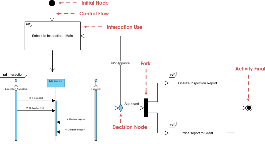
Activity Diagram
Models workflows, business processes, or algorithmic logic with support for decisions, loops, and parallel flows.

State Machine Diagram
Tracks how an object’s state changes in response to events—indispensable for modeling complex lifecycle logic.

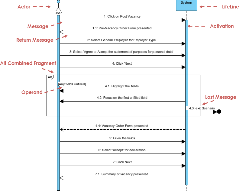
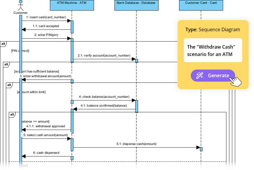
Sequence Diagram
Shows object interactions over time, emphasizing message order. Perfect for debugging distributed system flows.
Communication Diagram
Focuses on object relationships and message passing, with less emphasis on timing than sequence diagrams.

Interaction Overview Diagram
Provides a high-level flow of interactions, combining activity diagram structure with embedded interaction fragments.
Timing Diagram
Emphasizes time constraints and state changes over precise intervals—valuable for real-time or embedded systems.

My AI-Powered UML Workflow: From Idea to Diagram in Minutes
Here’s where my UML journey took a transformative turn. Traditional modeling tools required meticulous manual placement of elements—a barrier for rapid iteration. Then I discovered Visual Paradigm’s AI Diagram Generation, and the experience changed how I approach system design.
Why AI Changes the Game
-
Natural Language Input: Describe your system in plain English; the AI interprets entities and relationships
-
Standards-Compliant Output: Generated diagrams follow UML semantics, not just pretty pictures
-
Fully Editable Results: Output is native Visual Paradigm format—no dead-end exports
-
Intelligent Layout: The AI arranges elements logically, saving hours of manual alignment
My Step-by-Step Experience
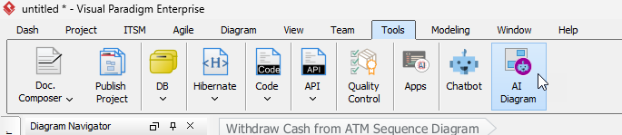
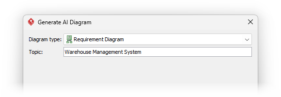
Step 1: Launch the AI Generator
Navigate to Tools > AI Diagram in Visual Paradigm. A clean interface appears, ready for your input.

Step 2: Select Your Diagram Type
Choose the context: Use Case, Class, Sequence, etc. This guides the AI’s interpretation rules.
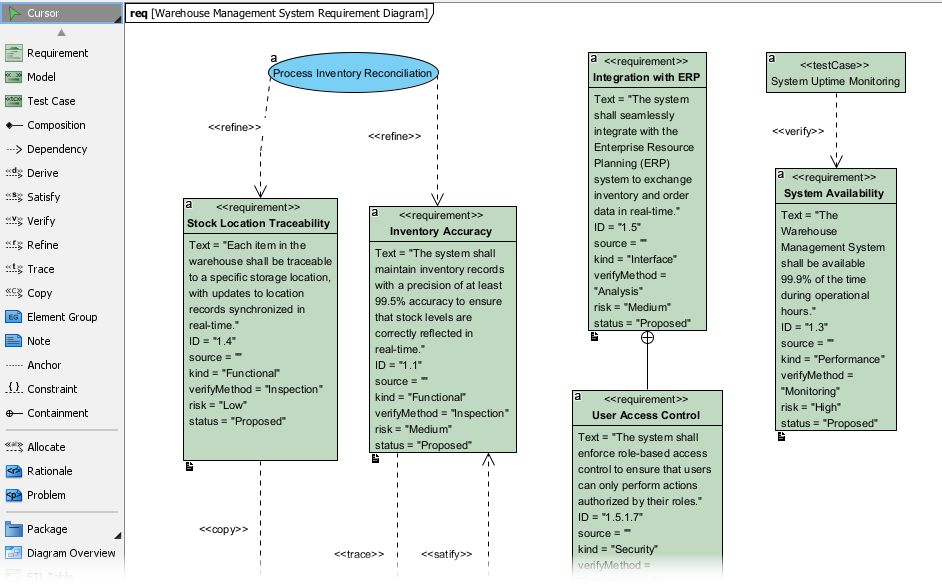
Step 3: Describe Your System in Plain Language
Be specific. Instead of “an e-commerce system,” try:
“An online bookstore where customers can search books by title or author, add items to a cart, apply promo codes, checkout with credit card or PayPal, and receive order confirmation emails.”
Step 4: Review and Refine
Click OK, and within seconds, a structured diagram appears—ready for editing.
Pro Tips from My Iterations
-
Start broad, then refine: Generate a high-level use case diagram first, then drill into sequence diagrams for complex flows
-
Use the AI output as a conversation starter, not a final artifact—collaborate with your team to validate assumptions
-
Leverage the editable nature: Add constraints, stereotypes, or documentation directly in the model
-
Combine with other tools: Export diagrams to Confluence via OpenDocs for living documentation
Practical Advice: Making UML Work in Real Projects
After months of applying UML in production environments, here are my hard-won insights:
-
Start Small: Don’t model everything. Focus on high-risk or high-ambiguity areas first.
-
Keep Diagrams Alive: Treat models as living artifacts. Update them when code changes, or they become technical debt.
-
Tailor to Your Audience: A class diagram for developers can include method signatures; one for stakeholders might show only key associations.
-
Use Layers of Abstraction: Create high-level overview diagrams, then link to detailed sub-diagrams for depth.
-
Integrate with Your Workflow: Embed diagram reviews in sprint planning or architecture decision records.
-
Embrace AI as a Catalyst, Not a Crutch: Let AI accelerate initial drafts, but apply human judgment for validation and refinement.
Conclusion: UML as Your Strategic Advantage
My journey with UML transformed it from an academic concept into a practical superpower. In a world where software complexity continues to escalate, the ability to visualize, communicate, and validate system design isn’t just helpful—it’s essential.
What excites me most is how modern tooling has lowered the barrier to entry. AI-powered diagram generation doesn’t replace deep modeling expertise; it amplifies it. By handling the mechanical aspects of diagram creation, these tools free us to focus on what truly matters: architectural thinking, stakeholder alignment, and risk mitigation.
If you’re on the fence about investing time in UML, I encourage you to start with one diagram type that addresses a current pain point. Maybe it’s a use case diagram to clarify requirements, or a sequence diagram to debug a tricky integration. Pair it with a free tool like Visual Paradigm Community Edition, and experiment.
The goal isn’t UML purity—it’s better software, delivered faster, with fewer surprises. And in that mission, UML remains one of our most versatile allies.
References
-
UML Specification: Official specification document for the Unified Modeling Language maintained by the Object Management Group.
-
Object Modeling Technique (OMT): Wikipedia overview of James Rumbaugh’s OMT methodology, a precursor to UML focused on analysis and data-intensive systems.
-
James Rumbaugh: Biographical information about one of the “Three Amigos” who co-created UML.
-
Grady Booch: Wikipedia profile of the software engineer known for the Booch method and contributions to object-oriented design.
-
Ada Programming Language: Background on the programming language that influenced early object-oriented techniques used in UML’s development.
-
Ivar Jacobson: Information about the creator of use cases and OOSE, a key contributor to UML’s behavioral modeling capabilities.
-
Object Management Group (OMG): The standards consortium responsible for adopting and maintaining the UML specification.
-
Visual Paradigm Community Edition Download: Free download page for the award-winning UML modeling tool that supports all diagram types.
-
Class Diagram Guide: Detailed tutorial on creating and interpreting UML class diagrams for object-oriented design.
-
Component Diagram Guide: Practical guide to modeling software component architectures and dependencies.
-
Deployment Diagram Guide: Instructions for visualizing software artifact deployment to hardware infrastructure.
-
Object Diagram Guide: Explanation of how object diagrams capture runtime instances and data values.
-
Package Diagram Guide: Tutorial on organizing model elements into packages and managing dependencies.
-
Composite Structure Diagram Guide: Guide to modeling internal class structures and collaborations.
-
Profile Diagram Guide: Instructions for creating domain-specific UML extensions using stereotypes.
-
Use Case Diagram Guide: Comprehensive resource for capturing functional requirements through actors and use cases.
-
Activity Diagram Guide: Tutorial on modeling workflows, business processes, and algorithmic logic.
-
State Machine Diagram Guide: Guide to visualizing object lifecycles and state transitions.
-
Sequence Diagram Guide: Instructions for modeling time-ordered object interactions and message flows.
-
Communication Diagram Guide: Resource for focusing on object collaborations and message passing.
-
Interaction Overview Diagram Guide: Tutorial on high-level interaction flow modeling with embedded fragments.
-
Timing Diagram Guide: Guide to modeling time-constrained behaviors and state changes.
-
AI Diagram Chatbot: Interactive AI assistant for generating and refining diagrams through natural language conversation.
-
Desktop AI Generator Guide: Step-by-step instructions for using AI diagram generation within Visual Paradigm Desktop.
-
OpenDocs Knowledge Management: Tool for embedding AI-generated diagrams into living documentation systems.
-
AI Diagram Generation Ecosystem Guide: Overview of Visual Paradigm’s integrated AI modeling capabilities.
-
Visual Paradigm Homepage: Official website for the award-winning modeling and collaboration platform.
-
Download Visual Paradigm: Central download portal for Visual Paradigm editions and trials.
-
AI Diagram Generation Features: Detailed overview of AI-powered diagram creation capabilities.
-
AI Generator: DFD & ERD Support: Announcement of expanded AI support for Data Flow and Entity Relationship Diagrams.
-
AI Generator: Package Diagrams: Release notes for AI-generated package diagram functionality.
-
AI Generator: Radar Charts: Announcement of AI-powered radar chart generation for capability visualization.
-
ArchiMate Diagrams with AI Tutorial: In-depth guide to generating enterprise architecture models using AI.
-
AI Timing Diagram Support: Release notes for AI-enhanced UML timing diagram generation.
-
AI ArchiMate in Desktop Tutorial: Step-by-step guide for AI-powered enterprise architecture modeling in desktop environments.
-
Visual Paradigm AI for ArchiMate: Article explaining how AI automates and enhances ArchiMate diagram creation.
-
AI Test Case Generation from Use Cases: Guide to leveraging AI for automatically deriving test scenarios from use case models.