In the fast-paced world of software development, time is a critical resource. Traditional UML modeling often requires hours of manual diagramming, dragging shapes, and aligning connectors. However, with the advent of AI-powered tools like Visual Paradigm, developers and product managers can now generate complete, professional-grade software models in minutes using natural language descriptions.

This article explores how Visual Paradigm’s AI capabilities transform text into structured UML diagrams, complete with practical PlantUML code examples that demonstrate the underlying logic behind these AI-generated models.
Core Capabilities: From Text to Diagram
Text-to-Diagram Generation Engine
Visual Paradigm features a Prompt-to-Diagram Generation Engine that allows users to input natural language descriptions and instantly generate structured UML diagrams. Instead of manually placing classes and drawing relationships, you simply describe your system:
“Create a class diagram for an e-commerce system with Customers, Orders, Products, and Payments. A Customer can place multiple Orders. Each Order contains multiple Products. Each Order has one Payment.”
The AI engine understands, structures, and creates professional diagrams automatically. This generative modeling capability transforms ideas into presentation-ready diagrams in seconds.
Supported UML Diagram Types
Visual Paradigm’s AI supports a comprehensive range of UML diagram types:
-
Class Diagrams – AI-assisted generator with suggestions, validation, PlantUML export, and design analysis
-
Use Case Diagrams – Instantly generates from text descriptions with advanced editing tools for refinement
-
Activity Diagrams – Converts text flows into visual, structured UML Activity Diagrams automatically
-
Component Diagrams – Generates professional component diagrams to streamline system architecture
-
SysML Requirement Diagrams – Transforms natural language into precise SysML requirement diagrams
Practical Examples: PlantUML Code Behind AI-Generated Diagrams
When Visual Paradigm’s AI generates a diagram, it often leverages standardized modeling languages like PlantUML under the hood. Below are complete examples of what the AI produces when you provide specific prompts.
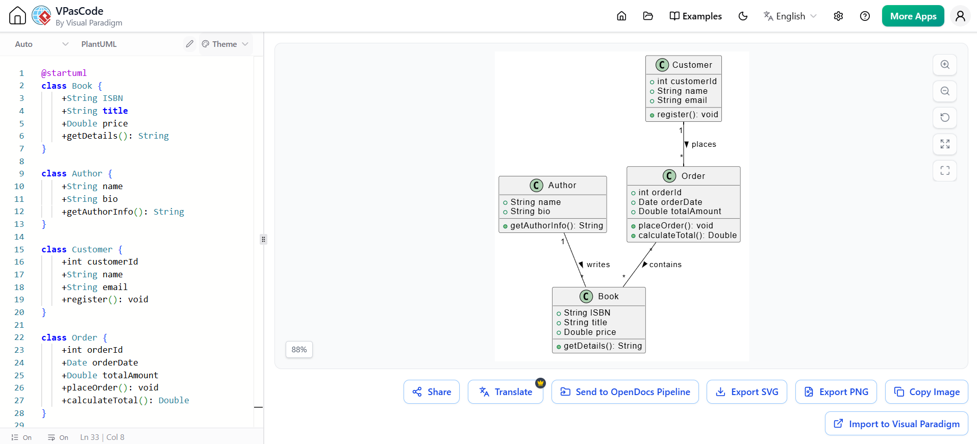
Example 1: Class Diagram for an E-Commerce System
User Prompt:
“Generate a class diagram for an online bookstore. Include classes for Book, Author, Customer, and Order. An Author writes many Books. A Customer places many Orders. Each Order contains multiple Books.”
AI-Generated PlantUML Code:
@startuml
class Book {
    +String ISBN
    +String title
    +Double price
    +getDetails(): String
}

class Author {
    +String name
    +String bio
    +getAuthorInfo(): String
}

class Customer {
    +int customerId
    +String name
    +String email
    +register(): void
}

class Order {
    +int orderId
    +Date orderDate
    +Double totalAmount
    +placeOrder(): void
    +calculateTotal(): Double
}

Author "1" -- "*" Book : writes >
Customer "1" -- "*" Order : places >
Order "*" -- "*" Book : contains >
@enduml
Key Features:
-
The AI correctly identifies multiplicity relationships (1-to-many, many-to-many)
-
Attributes and methods are inferred based on common domain knowledge
-
Relationships are labeled clearly for readability
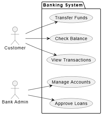
Example 2: Use Case Diagram for a Banking Application
User Prompt:
“Create a use case diagram for a banking app. Actors: Customer and Bank Admin. Customer can check balance, transfer funds, and view transactions. Admin can approve loans and manage accounts.”
AI-Generated PlantUML Code:
@startuml
left to right direction
actor Customer
actor "Bank Admin" as Admin

package "Banking System" {
    usecase "Check Balance" as UC1
    usecase "Transfer Funds" as UC2
    usecase "View Transactions" as UC3
    usecase "Approve Loans" as UC4
    usecase "Manage Accounts" as UC5
}

Customer --> UC1
Customer --> UC2
Customer --> UC3
Admin --> UC4
Admin --> UC5
@enduml
Key Features:
-
Actors are properly positioned (left-to-right layout for clarity)
-
Use cases are grouped within a system boundary package
-
Associations between actors and use cases are automatically established
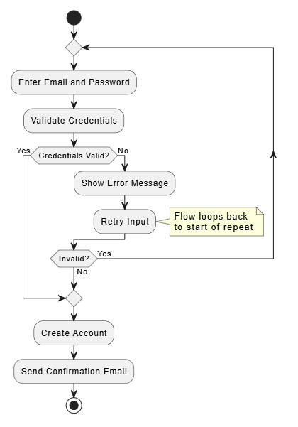
Example 3: Activity Diagram for User Registration Flow
User Prompt:
“Generate an activity diagram for user registration. Start with entering email and password. Validate credentials. If valid, create account and send confirmation email. If invalid, show error message and retry.”
AI-Generated PlantUML Code:
@startuml
@startuml
start
repeat
  :Enter Email and Password;
  :Validate Credentials;
  if (Credentials Valid?) then (Yes)
    break
  else (No)
    :Show Error Message;
  :Retry Input;
  note right
    Flow loops back
    to start of repeat
  end note
  endif
repeat while (Invalid?) is (Yes) not (No)
:Create Account;
:Send Confirmation Email;
stop
@enduml
Key Features:
-
Decision nodes are clearly marked with conditional branches
-
Flow logic follows standard programming patterns (if-else)
-
Start and end points are explicitly defined
Example 4: Component Diagram for a Microservices Architecture
User Prompt:
“Create a component diagram for a microservices-based e-commerce platform. Include components: API Gateway, User Service, Product Service, Order Service, and Payment Service. API Gateway routes requests to all services.”
AI-Generated PlantUML Code:
@startuml
package "E-Commerce Platform" {
    [API Gateway] as GW
    [User Service] as US
    [Product Service] as PS
    [Order Service] as OS
    [Payment Service] as PayS
}

GW --> US : routes to
GW --> PS : routes to
GW --> OS : routes to
GW --> PayS : routes to
@enduml
Key Features:
-
Components are grouped within a logical package
-
Dependencies are shown with directional arrows
-
Labels clarify the nature of interactions
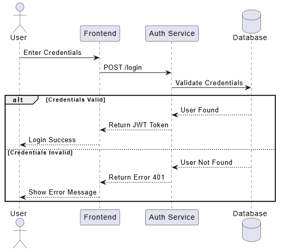
Example 5: Sequence Diagram for Login Process
User Prompt:
“Generate a sequence diagram for a user login process. User enters credentials. Frontend sends request to Auth Service. Auth Service validates with Database. If valid, return JWT token. If invalid, return error.”
AI-Generated PlantUML Code:
@startuml
actor User
participant "Frontend" as FE
participant "Auth Service" as AS
database "Database" as DB

User -> FE: Enter Credentials
FE -> AS: POST /login
AS -> DB: Validate Credentials
alt Credentials Valid
    DB --> AS: User Found
    AS --> FE: Return JWT Token
    FE --> User: Login Success
else Credentials Invalid
    DB --> AS: User Not Found
    AS --> FE: Return Error 401
    FE --> User: Show Error Message
end
@enduml
Key Features:
-
Lifelines represent each participant in the interaction
-
Alternative fragments (
alt) handle conditional logic -
Messages are labeled with HTTP methods and responses for technical accuracy
Key Features of Visual Paradigm’s AI Tooling
AI Chatbot Integration
Visual Paradigm provides an AI Chatbot Interface that offers instant diagram generation for UML, SysML, C4, ArchiMate, Mind Maps, and business strategy frameworks from simple text prompts. You can converse with the AI to refine diagrams iteratively.
Real-time Rendering
As the AI processes your requirements, you can view resulting diagrams visually in real time. This immediate feedback loop allows for rapid iteration and correction.
Clean Layout and Formatting
The AI generates clean, balanced, and readable diagrams with perfect spacing and alignment. This eliminates the tedious manual work of adjusting connector paths and resizing shapes.
Multi-platform Support
Visual Paradigm’s AI capabilities are available across:
-
Desktop Applications – Full-featured modeling environment
-
Chatbot Interfaces – Quick diagram generation via conversational AI
-
Web Apps – Browser-based access for collaborative teams
-
OpenDocs – Documentation integration for seamless workflow
Benefits for Development Teams
Speed and Efficiency
Generate complete software models in minutes rather than hours. What once took days of manual diagramming can now be accomplished in a single prompt session.
Accuracy and Validation
The AI validates designs against UML standards and provides intelligent suggestions for improvement. This reduces errors and ensures consistency across your documentation.
Focus on Design, Not Mechanics
By automating the mechanical aspects of diagram creation, teams can focus on ideas and architecture instead of manually arranging shapes and connectors.
Comprehensive Platform
Visual Paradigm is trusted as a comprehensive AI-enhanced visual modeling solution, supporting not just UML but also BPMN, ERD, flowcharts, and more.
Best Practices for Using AI-Generated UML Diagrams
-
Be Specific in Prompts: Provide clear, detailed descriptions including class names, relationships, and cardinalities.
-
Iterate and Refine: Use the AI chatbot to make incremental changes (e.g., “Add a method
cancelOrder()to the Order class”). -
Validate Output: Always review AI-generated diagrams for logical consistency and completeness.
-
Export and Integrate: Leverage PlantUML export features to integrate diagrams into version-controlled documentation.
-
Combine Manual and AI Workflows: Use AI for initial drafts, then refine manually for complex edge cases.
Conclusion
Visual Paradigm’s AI-powered UML diagram generation represents a significant leap forward in software modeling productivity. By transforming natural language descriptions into structured, professional diagrams, it empowers developers, architects, and product managers to communicate complex systems quickly and effectively.
Whether you’re designing a simple class structure or mapping out a complex microservices architecture, Visual Paradigm’s AI tooling enables you to generate complete software models in minutes—freeing you to focus on what matters most: building great software.
Ready to try it? Start with a simple prompt today and experience the power of AI-driven modeling firsthand.