
Master UML Inheritance: The Ultimate Guide to Generalization, “Is-A” Relationships, and Class Diagram Best Practices
When architects and developers design complex systems, the clarity of their diagrams determines the success of the project. Among the most critical patterns in Unified Modeling Language (UML) is inheritance, often referred to as generalization. This concept is not merely a drawing convention; it is the backbone of object-oriented design that allows for code reuse, logical hierarchy, and scalable architecture.
Whether you are a student learning the basics or a senior engineer refining a system model, understanding how to represent an “is-a” relationship correctly is essential. Below, we break down the core mechanics, visual standards, and strategic applications of UML inheritance to help you build robust class diagrams.
1. The 5 Core Concepts of UML Generalization
Before drawing a single line, you must internalize the theoretical framework that governs inheritance. These five concepts define the relationship between your classes:
- Generalization as Taxonomy: Generalization is fundamentally a taxonomic relationship. It organizes classifiers into a hierarchy, moving from the general (broad categories) to the specific (detailed instances).
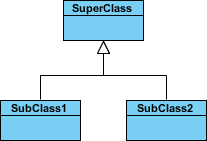
- The “Is-A” Relationship: This is the defining characteristic of inheritance. If SubClass1 inherits from SuperClass, it means SubClass1 is a SuperClass. This is distinct from “has-a” (aggregation/composition) relationships.
- Indirect Instances: Every instance of a specific classifier (child) is automatically an indirect instance of the general classifier (parent). You can treat a specific object wherever a general object is expected.
- Feature Inheritance: The specific classifier inherits the features (attributes and operations) of the general classifier. This reduces redundancy and ensures consistency across the hierarchy.
- Specialization: The process of creating a more specific classifier from a general one is called specialization. SubClass1 and SubClass2 are specializations of SuperClass.
2. The 3 Visual Standards for Drawing Inheritance in UML
Visual consistency is key to professional diagrams. While syntax can vary slightly between tools, the standard UML representation for inheritance is rigid. Here is how you must construct your diagrams:
- The Solid Line: The connection between the child and parent must always be a solid line. Dashed lines are reserved for realization (interface implementation), never for generalization.
- The Hollow Arrowhead: The line must terminate with a hollow (unfilled) triangle arrowhead. This specific shape is the universal symbol for “is-a” relationships in UML.
- Directional Flow (Child to Parent): Crucially, the arrowhead must point from the child element to the parent element. The tip of the triangle touches the general classifier, indicating that the specific class points up to its parent.
Pro Tip: In some diagramming tools, you may see alternative styles where the line is drawn differently, or the arrow is placed at the bottom. While these may be semantically equivalent in your specific tool’s engine, the solid line with a hollow arrow pointing to the parent is the industry standard for human readability.
3. How to Handle Abstract Classes in Your Diagrams
Not all classes are meant to be instantiated. In many systems, you define a general category that serves only as a template. UML has a specific notation to distinguish these from concrete classes:
- Italicized Names: If a class is abstract, its name must be written in italics. This immediately signals to the reader that this class cannot be created directly.
- Logical Placeholders: Abstract classes act as placeholders for common behavior. For example, in a Shapes system, a class named Shape might be abstract because you cannot draw a generic “Shape”; you can only draw a Circle or a Square.
- Inheritance Rules: Concrete subclasses (like SubClass1) inherit the abstract structure but must implement any abstract methods defined in the parent.
4. Real-World Application: The Shapes Inheritance Hierarchy
To visualize these concepts, consider a classic domain model involving geometric shapes. This example demonstrates how generalization simplifies complex logic:
- The Parent (SuperClass): Shape (Abstract). This class defines common attributes like
colorand operations likedraw(). - The Children (SubClasses): Circle and Rectangle. These are specializations of Shape.
- The Relationship: Circle is a Shape. Rectangle is a Shape.
- The Benefit: If you need to add a property like
area()to all shapes, you add it to Shape. Both Circle and Rectangle automatically inherit this capability without code duplication.
5. Critical Pitfalls to Avoid in Class Diagrams
Even experienced modelers make mistakes when representing inheritance. Avoid these common errors to ensure your diagrams remain valid and clear:
- Confusing “Is-A” with “Has-A”: Never use the hollow arrow for aggregation (e.g., a Car “has” an Engine). Use a diamond shape for aggregation, not a triangle for generalization.
- Reversing the Arrow: A common error is pointing the hollow arrow from the parent to the child. Remember: the arrow always points up to the general classifier.
- Missing Italics: Failing to italicize abstract class names can lead to confusion about which classes can be instantiated in the actual codebase.
- Over-Generalization: Do not force classes into an inheritance hierarchy if they only share a few attributes. If the “is-a” relationship is weak, consider composition or interfaces instead.
6. Best Practices for Scalable Inheritance Models
To maintain a healthy system architecture, follow these strategic guidelines when designing your class hierarchies:
- Limit Depth: Avoid creating deep inheritance chains (e.g., A inherits from B, which inherits from C, which inherits from D). Keep your hierarchy flat (2-3 levels max) to prevent complexity.
- Use Abstract Classes for Commonality: Only create abstract classes when there is truly shared behavior or state. If a class is too specific, make it concrete.
- Document the Semantics: If your inheritance relationship relies on complex business logic, add a note or comment to the diagram explaining the “is-a” relationship context.
- Ensure Single Responsibility: Each level of the hierarchy should have a clear, distinct responsibility. The parent defines the contract; the children define the implementation.
By mastering these principles, you transform UML class diagrams from simple sketches into powerful architectural blueprints. Whether you are visualizing a simple shapes system or a complex enterprise application, the rules of generalization remain your most reliable guide.