
Mastering BPMN Subprocesses in Visual Paradigm: From Abstract Loops to Detailed Flows
In the realm of Business Process Management (BPM), clarity is king. A single diagram that attempts to show every minute detail of a complex operation often becomes a tangled web that confuses stakeholders rather than clarifying the workflow. This is where the architectural concept of Subprocesses becomes indispensable. Visual Paradigm offers a robust environment for creating these nested layers of logic, allowing you to start with a high-level “Loop” concept and drill down into granular execution steps.
This tutorial explores the system architecture of hierarchical process modeling. We will walk through the transition from a simplified parent process to a detailed child process, demonstrating how to maintain the integrity of your data flow while managing complexity.
The Architecture of Hierarchical Modeling
Visual Paradigm’s approach to process modeling relies on the principle of abstraction. In the BPMN (Business Process Model and Notation) standard, a subprocess is essentially a container that encapsulates a set of activities. This allows you to treat a complex sequence of actions as a single, atomic task within a larger, overarching flow.
The Parent Flow: The High-Level View
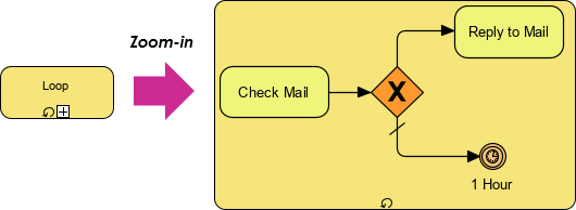
Consider the initial state of your diagram. You begin with a simplified representation of a business cycle. In our example, this is a process labeled “Loop.” This abstraction serves as the “Level 0” view. It tells the viewer that a cycle exists, but it hides the internal mechanics. The diagram might simply show a single task or a placeholder event.
The goal of the parent diagram is to establish the context. It defines the boundaries of the operation without getting bogged down in the “how.” By using a subprocess, you signal to the audience that this specific block of logic has depth, but that depth is currently being deferred for the sake of high-level readability.
Drilling Down: Creating the Subprocess
When the need arises to define the logic inside that “Loop,” Visual Paradigm provides several intuitive pathways to expand the model. You are not forced to start from scratch; you can evolve the diagram organically.
Method 1: The Resource Catalog Approach
One of the most powerful features in Visual Paradigm is the ability to leverage existing process libraries. If you have a standard workflow (like “Validate Order” or “Assess Return”) already defined in your organization’s Resource Catalog, you can drag it directly onto your diagram. The tool automatically recognizes the incoming and outgoing connections and wraps them into a subprocess container. This ensures consistency across your entire enterprise model.
Method 2: Context Menu Transformation
For ad-hoc modeling, you can select existing flow objects—tasks, gateways, and events—on your current diagram. By invoking the context menu, you can group these elements into a new subprocess. Visual Paradigm intelligently handles the wiring, creating a seamless internal flow while preserving the connection points on the parent diagram.
Deep Dive: The Expanded Workflow
Once the subprocess container is created, the architecture shifts from abstract to concrete. In the “Zoom-in” view of our example, we see the internal mechanics of the “Loop” process. This is where the business logic is truly defined.
- Start Event: The process initiates, likely triggered by an external event (e.g., a new email arrives).
- Task (Check Mail): The first actionable step. This is a manual or automated task where the system or user retrieves information.
- Exclusive Gateway (The “X”): This is the decision point. The model introduces a branch. The flow must choose a path based on a condition (e.g., “Is there a new message?” Yes vs. No).
- Parallel Paths:
- Path A (Reply to Mail): If the condition is met, the process proceeds to a specific task.
- Path B (Wait): If the condition is not met, the flow might enter a waiting state.
- Intermediate Timer Event: In the example, we see a timer icon labeled “1 Hour.” This is a crucial architectural element. It introduces a time-based constraint. The process pauses for a specific duration before re-evaluating or terminating, preventing infinite loops or ensuring timely responses.
This nested structure allows you to verify the internal logic (Start, Finish, Decision) without losing sight of the parent’s perspective.
Refining the View: Expansion and Preview
One of the most common challenges in BPMN modeling is balancing detail with visibility. Visual Paradigm addresses this with the Expand Sub-Process Preview option.
When enabled, this feature renders a miniature view of the internal subprocess directly onto the parent diagram. It is a “peek” at the complexity contained within. However, it is important to distinguish this from the actual expansion of the element. The preview is a visual aid for the parent view; it does not replace the need to open the child diagram for editing. This feature is invaluable for auditing, allowing you to verify that the internal flow matches the external expectations without cluttering the main diagram with thousands of pixels of detail.
Always review your diagram at both levels. The parent flow should be easy to understand at a glance, while the internal flow must have clear start and finish points to ensure the process doesn’t get “lost” inside the box.
Conclusion
Building a robust process model requires the ability to toggle between the forest and the trees. By utilizing Visual Paradigm’s subprocess capabilities, you can construct a system architecture that is both high-level enough for strategic planning and detailed enough for operational execution. Whether you are building a process from scratch using the Resource Catalog or grouping existing tasks into a logical unit, the key is maintaining the clear connection between the parent flow and the internal details.