
Modeling Car Architecture with VPasCode and UML Composite Structure Diagrams
In the realm of software architecture and systems engineering, understanding the internal composition of a system is often just as critical as understanding its external interfaces. While standard Class Diagrams focus on static relationships and attributes, Composite Structure Diagrams offer a deeper dive, revealing the “black box” inside a classifier and how its constituent parts interact.
This tutorial explores how to leverage VPasCode (Visual Paradigm as Code) to model these complex internal structures using a practical example: the architecture of a Car. We will walk through the syntax, the modeling logic, and the semantic meaning behind the connections.
Understanding the Composite Structure Diagram
A Composite Structure Diagram is a specialized view in the UML (Unified Modeling Language) that shows the internal parts of a classifier—such as a component or a class—and how those parts connect through ports. It is particularly useful when the internal collaboration matters more than the surrounding system architecture.
Unlike a standard deployment or class diagram, this view emphasizes:
- Parts: The specific components that make up the whole.
- Ports: The interaction points where communication happens.
- Connectors: The paths that allow data or control to flow between parts.
Step-by-Step: Modeling a Car’s Architecture
Using VPasCode, we can define this structure using a “class-diagram-style” sketch. While PlantUML does not provide a universally supported, dedicated composite-structure syntax in the same way standard UML tools do, we can effectively simulate it using component and port definitions within a package.
1. Setting the Stage: Class and Skinparam
We begin by defining the main classifier, the Car, and setting the visual style to ensure the output renders as rectangles (components) rather than standard classes.
@startuml
allowmixing
skinparam componentStyle rectangle

class Car {
}
2. Defining the Parts (Components)
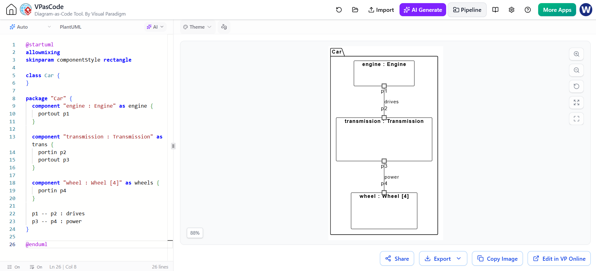
Inside the Car package, we define the internal subsystems. In this model, we treat the engine, transmission, and wheels as distinct components. We assign them specific types (e.g., Engine, Transmission) and aliases (e.g., as engine) for easier reference in connections.
package "Car" {
    component "engine : Engine" as engine {
        portout p1
    }
    component "transmission : Transmission" as trans {
        portin p2
        portout p3
    }
    component "wheel : Wheel [4]" as wheels {
        portin p4
    }
}
- engine : Engine: Represents the power source. It exposes an output port
p1. - transmission : Transmission: Represents the gearbox. It acts as a bridge, accepting input
p2and providing outputp3. - wheel : Wheel [4]: Represents the final drive mechanism. The notation
[4] indicates a composite structure where this single logical part represents four physical wheels, all sharing the input portp4.
3. Connecting the Dots: Ports and Connectors
The true power of the Composite Structure Diagram lies in the connectors. These lines define the flow of “drives” and “power” between the ports defined above.
    p1 -- p2 : drives
    p3 -- p4 : power
}
@enduml
This syntax creates a flow: The engine’s output (p1) connects to the transmission’s input (p2) via the “drives” connector. The transmission’s output (p3) connects to the wheels’ input (p4) via the “power” connector.
Interpreting the Resulting Diagram
When rendered in the VPasCode tool, this code generates a visual representation of the Car’s internal topology. You will see the Car frame containing the engine, transmission, and wheels boxes, with small squares representing the ports and lines representing the connectors.
Note on Semantics: Treat this as a structural sketch. While it conveys the parts and connections clearly, it does not show formal UML ports or connector semantics in their strictest specification form. It is a powerful tool for communicating architecture quickly.
Conclusion
By combining the textual precision of VPasCode with the visual clarity of composite structure concepts, you can effectively model complex internal systems. Whether you are designing software microservices or mechanical sub-systems, understanding how parts connect through ports is essential for a robust architecture.