


Building robust software systems requires more than just writing code; it demands a clear vision of how different components interact before a single line of implementation begins. At the heart of this strategic planning lies the class diagram, a fundamental tool within the Unified Modeling Language (UML) ecosystem. These diagrams serve as the blueprint for object-oriented design, allowing architects to visualize structure, behavior, and relationships in a way that is both human-readable and technically precise. By integrating class diagrams into the early phases of development, teams can identify potential architectural flaws, streamline communication, and ensure that the final product aligns with business requirements.
This guide explores the practical application of class diagrams in planning complex software architectures. We will examine the core elements, the strategic advantages of early modeling, and the methodologies used to translate abstract requirements into concrete structural designs. Whether you are a senior architect or a development lead, understanding these principles is essential for delivering scalable and maintainable systems.
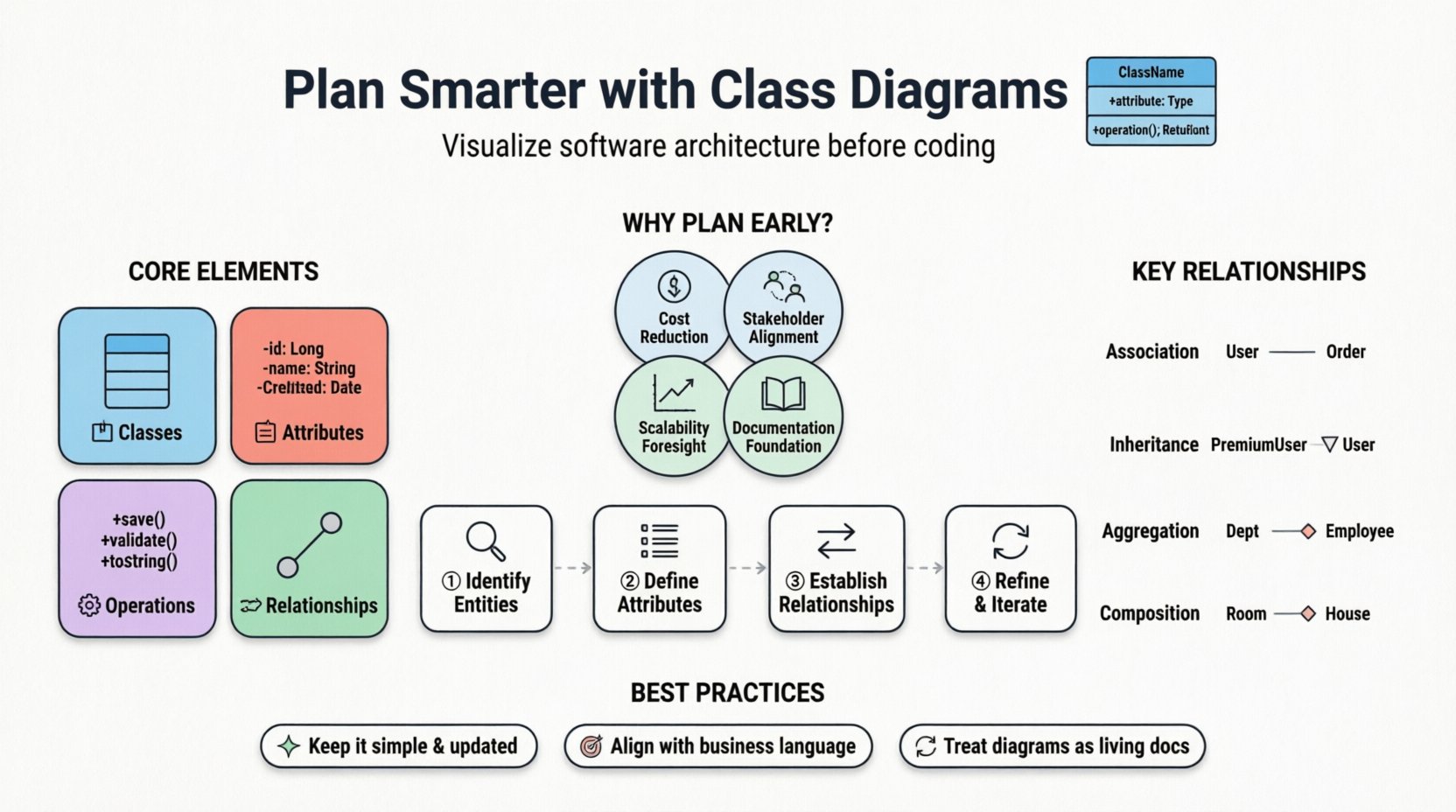
🔍 Understanding the Core Elements of Class Diagrams
A class diagram represents the static structure of a system. It describes the system’s classes, their attributes, operations (methods), and the relationships among objects. Unlike sequence diagrams which focus on time and flow, class diagrams focus on the nouns and their connections. To utilize them effectively for architecture planning, one must understand the building blocks.
- Classes: The fundamental unit representing a category of objects. In a diagram, a class is typically depicted as a rectangle divided into three sections: the class name, attributes, and operations.
- Attributes: These define the state or data held by an object. They represent properties such as user IDs, configuration settings, or data strings.
- Operations: These define the behavior or functionality available to the object. They include methods for processing data, retrieving information, or triggering actions.
- Relationships: These define how classes interact with one another. Common types include association, aggregation, composition, and inheritance.
When planning an architecture, these elements are not merely drawn; they are defined with specific constraints and responsibilities. The goal is to create a model that reflects the domain logic accurately, ensuring that the resulting codebase is intuitive and logical.
📈 Why Early Planning Matters for Complex Systems
Complexity in software architecture often stems from hidden dependencies and unclear responsibilities. Addressing these issues at the coding stage is expensive and time-consuming. Planning with class diagrams early offers several distinct advantages.
- Cost Reduction: Identifying structural issues during the design phase is significantly cheaper than refactoring code after deployment. Changes to a diagram take minutes; changes to a deployed system take days.
- Stakeholder Alignment: Diagrams provide a visual language that bridges the gap between technical teams and non-technical stakeholders. Business analysts can review the structure to ensure it matches their mental model of the business domain.
- Scalability Foresight: By mapping out relationships early, architects can spot potential bottlenecks. For instance, a tightly coupled relationship might indicate a need for abstraction or interface separation before implementation begins.
- Documentation Foundation: The diagram becomes the source of truth for the system’s structure. It serves as a reference for future onboarding, maintenance, and feature expansion.
Without this visual planning, teams often fall into the trap of “code-first” development, where the architecture emerges organically but often results in a tangled web of dependencies that is difficult to maintain.
🛠️ Step-by-Step Implementation Guide
Creating a class diagram for a complex architecture is a systematic process. It involves moving from broad requirements to specific implementation details. The following steps outline a logical workflow for this process.
1. Identify Core Entities and Requirements
The first step is to analyze the functional requirements. What are the primary objects in the system? In an e-commerce context, these might be Users, Orders, and Products. In a financial system, they might be Accounts, Transactions, and Audits.
- Read through the requirement specifications.
- Highlight nouns that represent persistent data or business entities.
- Draft initial class boxes for these entities.
- Ensure every major feature has at least one corresponding class representation.
2. Define Attributes and Data Types
Once the entities are identified, define what data they hold. This step forces a discussion about data granularity and types.
- For a User class, attributes might include username, email, and role.
- For an Order class, attributes might include orderID, timestamp, and totalAmount.
- Specify visibility modifiers (public, private, protected) to enforce encapsulation principles.
- Define data types explicitly to avoid ambiguity during implementation.
3. Establish Relationships
Classes rarely exist in isolation. They must communicate and interact. Defining these relationships is critical for understanding data flow and dependency.
- Association: A general link between two classes. For example, a User places an Order.
- Inheritance: A generalization relationship where a subclass inherits properties from a superclass. For example, a PremiumUser extends a StandardUser.
- Aggregation: A “has-a” relationship where the child can exist independently of the parent. For example, a Department has Employees.
- Composition: A stronger “part-of” relationship where the child cannot exist without the parent. For example, a House has Rooms.
4. Refine and Iterate
The initial draft is rarely perfect. Review the diagram for circular dependencies, excessive coupling, and missing responsibilities. Refine the design based on feedback from the team.
- Check for high coupling. If Class A and Class B depend heavily on each other, consider introducing an interface or mediator.
- Ensure the Single Responsibility Principle is respected. Each class should have one reason to change.
- Validate that the cardinality of relationships (one-to-one, one-to-many, many-to-many) matches the business rules.
🧩 Relationship Dynamics and Modeling
Understanding the nuances of relationships is where many architectural plans fail. A small change in how two classes are connected can have massive implications for database design and code modularity. The table below summarizes the key relationship types and their architectural implications.
| Relationship Type | Visual Notation | Meaning | Architectural Implication |
|---|---|---|---|
| Association | Solid Line | Objects know about each other | Direct dependency; requires import or reference |
| Inheritance | Solid Line with Hollow Triangle | Specialization of a base class | Promotes code reuse but increases tight coupling |
| Aggregation | Line with Hollow Diamond | Whole-Part relationship (independent) | Part can exist without the Whole; shared lifecycle |
| Composition | Line with Filled Diamond | Whole-Part relationship (dependent) | Part lifecycle tied to Whole; strong ownership |
| Dependency | Dashed Line with Open Arrow | Usage relationship | Temporary usage; often method parameters or local variables |
When planning, choose the relationship that best reflects the real-world constraint. For example, using Composition for a Car and Engine implies that if the Car is destroyed, the Engine is also effectively destroyed in that context. Using Aggregation for a Car and a Driver implies the Driver can exist without the specific Car instance.
🧱 Managing Complexity and Abstraction
As systems grow, class diagrams can become overwhelming. A single diagram for a massive enterprise application might contain hundreds of classes. To maintain clarity, abstraction techniques are necessary.
- Package Diagrams: Group related classes into packages or namespaces. This allows you to see the high-level organization without getting bogged down in individual method details.
- Interfaces: Define contracts that classes must implement. This separates the “what” from the “how” and allows for flexible implementation swapping.
- Abstract Classes: Use these to define common behavior for a group of related classes without forcing implementation details.
- Sub-diagrams: Create detailed diagrams for specific modules (e.g., Authentication Module, Payment Module) and link them to the main overview diagram.
Abstraction is not about hiding information; it is about managing cognitive load. A developer should not need to see every attribute of the entire system to understand a specific feature. Layered design supports this by isolating concerns.
🔄 From Diagram to Code
The ultimate test of a class diagram is how well it translates into code. While some tools support reverse engineering (generating diagrams from code), the best practice is forward engineering: code generation or manual implementation guided by the diagram.
When implementing the design:
- Verify Consistency: Ensure the implemented class structure matches the diagram. If the code diverges, update the diagram.
- Enforce Constraints: Use access modifiers in the code to match the visibility defined in the diagram (public vs. private).
- Handle Polymorphism: If the diagram uses inheritance, ensure the code leverages polymorphism correctly to allow for flexible behavior.
- Refactor as Needed: It is common to discover edge cases during coding that require a slight adjustment to the design. This is normal. The diagram is a living document, not a static contract.
⚠️ Common Pitfalls in Design
Even experienced architects can fall into traps when planning. Being aware of these pitfalls helps in avoiding them.
- Over-Engineering: Creating complex inheritance hierarchies that are difficult to maintain. Often, a simple composition or delegation is better than deep inheritance trees.
- Under-Designing: Skipping the diagram entirely and relying on intuition. This leads to inconsistent naming and scattered logic.
- Ignoring Data Flow: Focusing only on structure without considering how data moves between classes. This can lead to performance bottlenecks.
- Static Coupling: Creating too many direct dependencies between classes. This makes the system brittle and hard to test in isolation.
- Ignoring Persistence: Designing classes that do not align with the database schema. Object-Relational Mapping (ORM) mismatches can cause significant friction later.
🔮 Maintenance and Evolution
Software is never finished. Features are added, requirements change, and technologies evolve. The class diagram must evolve with the system.
- Version Control for Diagrams: Treat diagrams like code. Store them in the same repository and commit changes alongside code updates.
- Review Cycles: Include diagram reviews in the code review process. If a new class is added, the diagram should be updated.
- Legacy Code: For existing systems, creating a diagram can be a valuable exercise to understand the current state before refactoring.
- Documentation: Use the diagram to document API contracts and data structures for external consumers of the system.
🤝 Strategic Alignment with Business Goals
Technical architecture should serve business goals. A class diagram is a technical artifact, but it should reflect business rules.
- Domain-Driven Design: Align class names with the ubiquitous language of the business. If the business calls it a “Customer Order,” the class should be
CustomerOrder, notCOorOrderEntity. - Business Rules: If a business rule states a user cannot place an order without verification, the class diagram should reflect the necessary verification state or class dependency.
- Scalability Requirements: If the business expects high growth, the diagram should account for horizontal scaling patterns, such as sharding or load-balancing strategies, reflected in the data structure.
By keeping the business context in mind, the architecture remains relevant. A technically perfect system that does not solve the business problem is a failure. The class diagram bridges this gap by making the business logic visible in the code structure.
🎯 Best Practices for Clarity
To ensure the diagram remains useful over time, adhere to these best practices.
- Consistent Naming: Use standard naming conventions. Avoid abbreviations unless they are universally understood in the domain.
- Minimal Detail: Do not list every single method in the diagram unless it is critical for the design discussion. Focus on public interfaces and key attributes.
- Logical Grouping: Keep related classes close together visually. Use boundaries or packages to indicate boundaries.
- Clear Notation: Use standard UML notation consistently. Do not invent custom symbols that only you understand.
- Regular Updates: A stale diagram is worse than no diagram. Keep it synchronized with the codebase.
🚀 Conclusion on Architectural Planning
Planning complex software architectures requires discipline and foresight. Class diagrams provide a structured method to achieve this. They allow teams to visualize the system’s skeleton, identify risks, and agree on a shared understanding before the heavy lifting of coding begins. While they do not guarantee success, they significantly increase the probability of building a system that is robust, scalable, and maintainable.
By following the steps outlined in this guide—identifying entities, defining relationships, managing complexity, and maintaining alignment with business goals—teams can leverage class diagrams as a strategic asset. The investment in early planning pays dividends in reduced technical debt and smoother development cycles. As you move forward with your next project, consider the class diagram not as an optional artifact, but as a foundational component of your engineering strategy.