


Creating a system architecture is not merely about drawing shapes and connecting lines. It is about establishing a shared language between technical teams and business owners. One of the most powerful tools in this communication arsenal is the Interaction Overview Diagram (IOD). This diagram type bridges the gap between high-level activity flows and detailed sequence interactions. However, a diagram that looks perfect on screen may fail to capture the actual needs of the people who will build, test, or use the system.
Validation is the critical step that ensures your design aligns with reality. Without rigorous checking, even the most elegant model can lead to costly rework later in the development lifecycle. This guide provides a structured approach to verifying your diagrams, ensuring they meet the technical and functional requirements of your stakeholders.
🧩 Understanding the Interaction Overview Diagram
Before validating, one must understand the artifact. An Interaction Overview Diagram is a structured activity diagram that focuses on the control flow of interaction between objects. It combines elements of Activity Diagrams and Sequence Diagrams. Instead of showing every single message exchange in a linear sequence, an IOD allows you to show the flow of control between different interaction fragments.
- Control Flow: It dictates the order of operations, loops, and conditional branches.
- Object Lifelines: It references specific lifelines found in detailed sequence diagrams.
- Activity Nodes: It uses rounded rectangles to represent actions or sub-flows.
- Decision Nodes: It handles branching logic based on conditions.
When stakeholders review this diagram, they are not looking for syntax perfection. They are looking for logic correctness. Does the flow match the business process? Do the boundaries of the system align with expectations? Validation ensures these questions are answered before code is written.
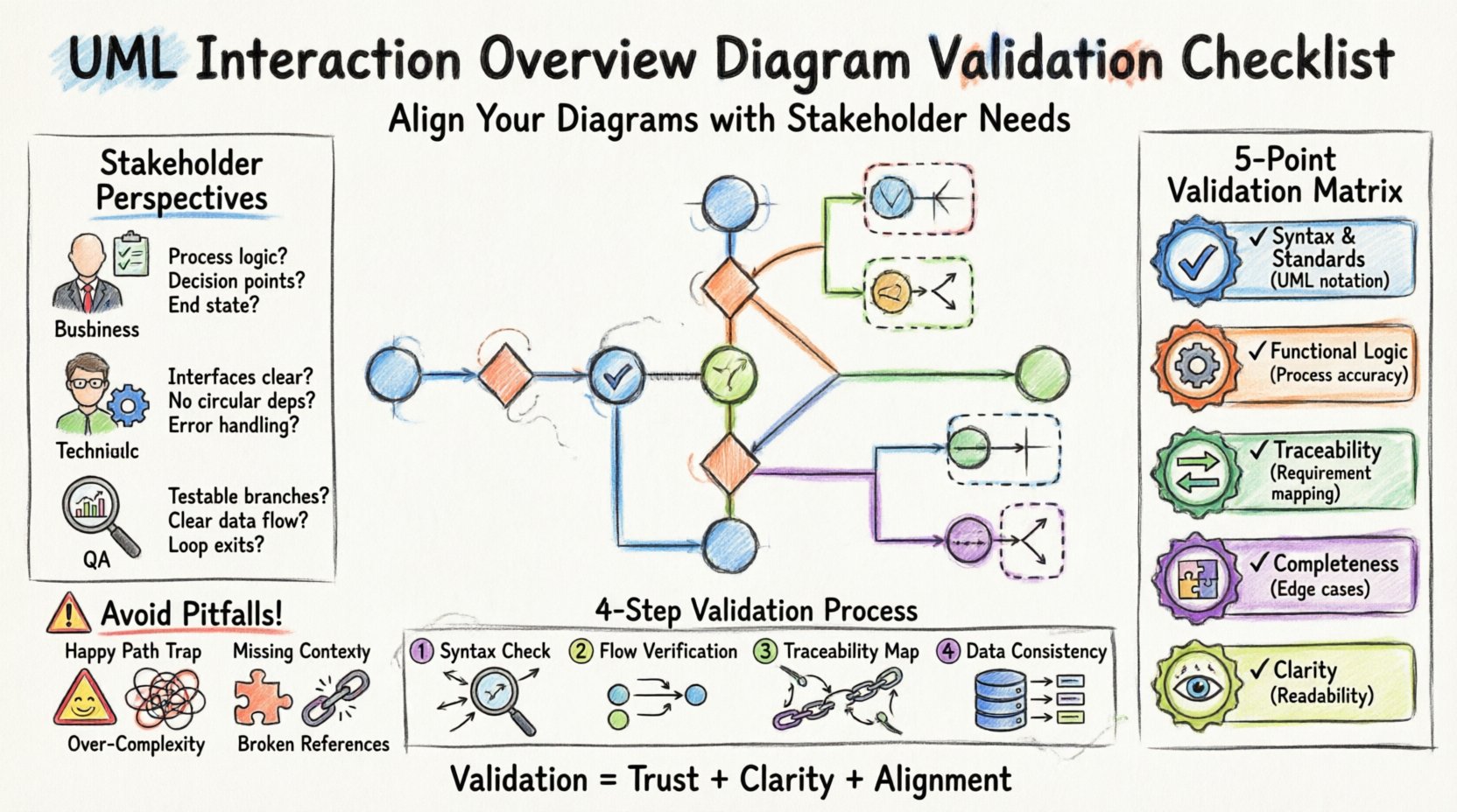
👥 Identifying Stakeholder Requirements
Validation is impossible without clear stakeholder criteria. Different groups care about different aspects of the diagram. A checklist must account for these varied perspectives to ensure comprehensive coverage.
Business Stakeholders
These individuals focus on process logic and value delivery. They do not care about message sequencing details but care deeply about whether the workflow matches their operational procedures.
- Does the flow represent the actual business process?
- Are all decision points covered (e.g., if payment fails)?
- Is the end state achievable within the defined scope?
Technical Stakeholders
Developers and architects focus on feasibility and integration points. They need to know if the interactions are technically viable.
- Are the interfaces defined clearly in the referenced sequence diagrams?
- Are there circular dependencies that might cause issues?
- Is error handling explicitly defined for critical paths?
Quality Assurance Stakeholders
Testers need to know how to verify the system behavior. The diagram serves as a blueprint for test cases.
- Are all branches reachable for testing?
- Is the data flow clear for test data preparation?
- Are the exit conditions for loops clearly defined?
📊 The Validation Matrix
To streamline the review process, it is helpful to organize criteria into a structured matrix. This table categorizes validation points by their nature, ensuring no aspect is overlooked during the review session.
| Category | Validation Focus | Key Question |
|---|---|---|
| Syntax & Standards | UML Conformance | Does the diagram follow standard notation rules? |
| Functional Logic | Process Accuracy | Does the flow match the business requirement? |
| Traceability | Requirement Mapping | Can each node be traced back to a requirement? |
| Completeness | Edge Cases | Are error paths and alternative flows included? |
| Clarity | Readability | Can a new team member understand the flow? |
🔍 Step-by-Step Validation Process
Executing the validation requires a methodical approach. Rushing through this phase often results in missed defects. Follow this sequence to ensure thoroughness.
1. Syntax and Notation Check
Start with the basics. Ensure the diagram adheres to the Unified Modeling Language (UML) standards. While tools can automate some of this, human review is essential for context.
- Verify that all activity nodes are properly connected.
- Check that decision nodes have explicit ‘true’ and ‘false’ labels on outgoing edges.
- Ensure that join nodes (synchronization bars) match the number of incoming flows.
- Confirm that interaction fragments (like
alt,opt,loop) are correctly referenced if nested.
2. Functional Flow Verification
This is the core of stakeholder alignment. Walk through the diagram as if you were the system executing the logic.
- Start Point: Is there a clear initial node? Is it obvious how the process begins?
- End Point: Are there termination nodes? Is it clear when the process stops?
- Loops: Do loops have a defined exit condition? Infinite loops are a common design flaw.
- Branches: Do all paths eventually converge or terminate? Dead ends are unacceptable.
3. Traceability to Requirements
Every major interaction or decision should map to a documented requirement. This prevents scope creep and ensures the model solves the right problem.
- Link activity nodes to specific user stories or functional specifications.
- Highlight areas where requirements are vague or missing.
- Ensure that any feature not in the requirements is explicitly flagged as out-of-scope.
4. Data and Object Flow Consistency
Interaction Overview Diagrams often reference objects. Ensure the data passing through these interactions is consistent with the system model.
- Check that input parameters match the object types defined in the class model.
- Verify that state changes are consistent with the state machine diagrams, if applicable.
- Ensure that object creation and destruction happen at logical points in the flow.
⚠️ Common Pitfalls and How to Avoid Them
Even experienced modelers can fall into traps. Recognizing these patterns early saves significant time during the review phase.
The ‘Happy Path’ Trap
Many diagrams only show the ideal scenario. If a user cancels a transaction, what happens? If the network fails, what happens?
- Fix: Explicitly model exception flows. Use decision nodes to handle negative outcomes.
- Fix: Ask stakeholders, “What could go wrong here?” during the validation session.
Overly Complex Branching
A diagram with too many nested decision nodes becomes unreadable. This confuses stakeholders and obscures the main logic.
- Fix: Refactor complex logic into sub-activities or separate diagrams.
- Fix: Use comments or notes to clarify complex conditions rather than cluttering the flow.
Lack of Context
Diagrams often exist in isolation. Without context, a sequence of actions makes no sense.
- Fix: Always provide a brief narrative description alongside the diagram.
- Fix: Ensure the scope boundary is clear. What is inside the system and what is external?
Disconnected Fragments
In an Interaction Overview, you often reference Sequence Diagrams. If those references are broken or outdated, the IOD loses value.
- Fix: Maintain a strict version control link between the IOD and the referenced sequence diagrams.
- Fix: Periodically audit references to ensure the underlying interactions have not changed.
🗣️ Conducting the Stakeholder Review
The validation process culminates in a review session. This is where the diagram meets the people who will approve it. A successful review relies on preparation and facilitation.
Preparation
Do not simply present the diagram. Prepare a walkthrough script.
- Identify the specific goals of the meeting.
- Send the diagram to attendees in advance so they can review it before the meeting.
- Prepare a list of specific questions to ask, rather than waiting for general feedback.
Facilitation
During the session, guide the conversation to keep it productive.
- Encourage stakeholders to speak in terms of business value, not technical implementation details.
- Record all feedback, even if it seems minor.
- Resolve conflicts by referring back to the documented requirements.
Documentation
After the meeting, document the changes made based on the feedback.
- Create a change log that tracks what was modified and why.
- Update the diagram version number.
- Notify all relevant parties of the updated baseline.
🔄 Iteration and Continuous Improvement
Validation is not a one-time event. Requirements change, and the system evolves. The diagram must evolve with them.
- Change Management: Establish a protocol for updating diagrams when requirements shift.
- Periodic Audits: Schedule regular reviews of the model to ensure it remains aligned with the current system state.
- Knowledge Sharing: Use the validated diagram as a training tool for new team members to understand system behavior.
🛠️ Practical Application Tips
To make validation easier in your daily workflow, consider these practical strategies.
- Color Coding: Use different colors for different types of flows (e.g., normal, error, timeout) to improve visual scanning.
- Annotations: Add text notes directly on the diagram to explain complex business rules that are not obvious from the flow alone.
- Modularization: Break large diagrams into smaller, manageable sections. This makes it easier for stakeholders to focus on specific areas.
- Tooling: Use modeling environments that support traceability matrices. This allows you to click a diagram element and see the associated requirement instantly.
🎯 Final Thoughts on Alignment
Validating an Interaction Overview Diagram is about more than checking boxes. It is about building trust between the technical team and the business. When a diagram accurately reflects stakeholder needs, it becomes a reliable contract for development.
By following a structured checklist, engaging diverse perspectives, and maintaining a rigorous review process, you ensure that your system design is robust, clear, and aligned. This discipline reduces risk and increases the likelihood of delivering a solution that truly meets the intended purpose. Invest time in the validation phase, and the clarity it brings will pay dividends throughout the entire project lifecycle.
Remember, the goal is clarity, not perfection. A well-validated diagram is a tool for communication, not just a document for storage. Keep the focus on the human element—ensuring that everyone involved understands the flow of the system exactly as intended.