


Introduction to Modern Software Modeling
In the complex world of software architecture, clarity is paramount. As systems grow from simple applications into distributed microservices and intricate enterprise solutions, the ability to visualize the structural relationships between various software modules becomes critical. This is where the Unified Modeling Language (UML) Component Diagram steps in as an essential artifact. However, manually drawing these diagrams can be time-consuming and prone to layout errors.
With the advent of Artificial Intelligence, the landscape of modeling is shifting. Tools like Visual Paradigm are leading the charge by integrating AI to automate the generation of these diagrams. This guide explores the fundamentals of Component Diagrams, offers step-by-step guidelines for creating them, and highlights how the latest updates to Visual Paradigm’s AI Chatbot have revolutionized the process with improved stability, layout quality, and accuracy.
Key Concepts: Understanding UML Component Diagrams
Before diving into automation, it is vital to understand the foundational elements that make up a Component Diagram. These diagrams provide a high-level view of the static structure of a system, focusing on the components and the dependencies between them.
1. Components
A Component represents a modular part of a system that encapsulates its contents and whose manifestation is replaceable within its environment. In UML, this is typically depicted as a rectangle with the component’s name, optionally including a small icon in the top right corner. Components can be anything from a database, a subsystem, a web server, or a specific functional module like “Order Processing.”
2. Interfaces
Components communicate with each other through Interfaces. These define a set of operations that a component provides or requires. Understanding the distinction is crucial for a clean diagram:
- Provided Interface: A collection of functionalities that a component offers to other components. It is graphically represented by a circle attached to the component (often called a “lollipop”).
- Required Interface: A collection of functionalities that a component needs from others to function. This is represented by a semi-circle attached to the component (often called a “socket”).
3. Connectors and Dependencies
Connectors link components together, typically connecting a required interface of one component to the provided interface of another. This wiring represents the dependency relationship, showing how data or control flows between different parts of the system.
VP AI: Automating and Enhancing Component Diagrams
Visual Paradigm has introduced a major upgrade to its AI Chatbot for visual modelers, specifically targeting the generation of UML Component Diagrams. This tool leverages natural language processing to convert text descriptions into professional-grade diagrams. The latest update addresses three critical areas that historically plague automated diagramming: layout, stability, and relevance.
Vastly Improved Diagram Layout
One of the most significant challenges in auto-generating diagrams is the “spaghetti code” visual effect—lines crossing everywhere and overlapping elements. Visual Paradigm’s overhauled layout engine addresses this directly:
- Clearer Interfaces: The AI now distinctly renders Required and Provided interfaces, strictly adhering to conventional UML standards. This ensures that the “handshake” between components is visually obvious.
- Uncluttered Connectors: The algorithm has been optimized to minimize overlapping connector lines. The result is a tidy, professional structure where relationships are easy to trace without visual noise.
Enhanced Stability and Reliability
Consistency is key in professional workflows. Visual Paradigm has significantly improved the stability of the generation process. This reduces the frequency of generation failures, ensuring that when a user inputs a prompt, the system reliably produces a result. This improvement minimizes the frustration of failed attempts and creates a smoother workflow for architects and developers.
Context-Aware Accuracy
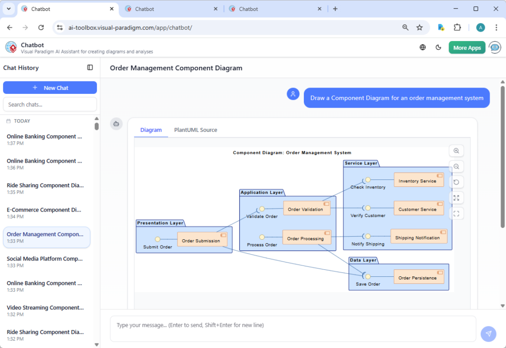
The updated AI engine adheres more closely to user input prompts. By better understanding the context of the request—whether it is an Order Management System or a Social Media Platform—the AI aligns the generated components and relationships more accurately with the user’s description. This reduces the need for manual post-generation adjustments.
Guidelines: Creating Effective Component Diagrams with AI
To get the most out of AI-powered modeling, follow these structured guidelines when formulating your requests and refining your diagrams.
Step 1: Define the Scope
Before prompting the AI, determine the boundaries of the system you are modeling. Are you modeling a single monolith, a set of microservices, or a specific subsystem? Clear boundaries prevent the AI from generating an overly complex or fragmented diagram.
Step 2: Crafting the Prompt
The quality of the output depends on the quality of the input. When using the Visual Paradigm AI Chatbot, structure your prompt to include key functional areas. For example:
“Produce a Component Diagram for a social media platform showing the components responsible for user profiles, content creation, feed generation, messaging, media storage, and moderation services.”
Listing specific responsibilities helps the AI identify the necessary components and infer the relationships between them.
Step 3: Analyze Interfaces
Once the AI generates the initial draft, review the interfaces. Look for the “lollipop” and “socket” connections. Ensure that every component that requires a service is connected to a component that provides it. Thanks to the new layout engine, these connections should be distinct and easy to verify.
Step 4: Refine and Iterate
Use the generated diagram as a baseline. You can refine the diagram by adding specific technical constraints or third-party integrations (e.g., specific payment gateways or external APIs) that the generic AI model might not assume unless prompted.
Tips and Tricks for Optimization
Here are some expert tips to maximize efficiency when using Visual Paradigm’s AI tools for Component Diagrams:
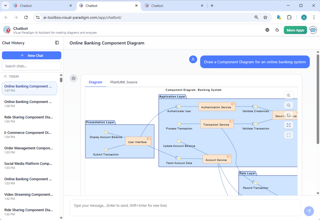
- Use Iterative Prompting: If the initial diagram is too simple, do not discard it. Add detail to your prompt and regenerate. For example, append “Include a security component that handles authentication for all other modules” to the original prompt.
- Focus on Verb-Noun Pairs: When describing components in your prompt, use action-oriented language (e.g., “manage orders,” “process payments,” “store logs”). This helps the AI differentiate between a database (storage) and a service (processing).
- Leverage the text-to-model Feature: If you have existing documentation, summarize the architecture into a paragraph and feed it to the AI. The enhanced context awareness will map your specific architectural narrative to standard UML elements.
- Check Connector Flow: Even with improved layouts, always double-check the direction of dependencies. A component diagram should generally flow logically, often from the user interface layers down to data storage layers.
Conclusion
The integration of AI into UML modeling represents a significant leap forward for system architects and developers. With Visual Paradigm’s latest upgrades to their AI Chatbot, the barriers to creating accurate, clean, and standard-compliant Component Diagrams have been lowered. By combining a solid understanding of UML concepts with these advanced AI capabilities, professionals can accelerate their design process, ensure architectural consistency, and communicate complex system structures with clarity.