


Software design is the backbone of any robust application, yet the barrier to entry for creating professional diagrams is often high. Between mastering complex syntax and ensuring architectural consistency, developers and students often struggle to visualize their ideas effectively. The AI-Assisted UML Class Diagram Generator bridges this gap by combining an intuitive step-by-step wizard with powerful artificial intelligence. This tool allows users to go from a vague idea to a professionally analyzed UML diagram without writing a single line of manual code.
This tutorial explores how to leverage this browser-based tool to accelerate your workflows, whether you are a student learning the ropes or a professional architect communicating complex systems.
Key Concepts
Before diving into the workflow, it is essential to understand the core technologies and methodologies that drive this generator.
UML Class Diagrams
The Unified Modeling Language (UML) is the industry standard for visualizing software systems. A Class Diagram is a type of static structure diagram that describes the structure of a system by showing the system’s classes, their attributes, operations (or methods), and the relationships among objects. It is the blueprint of object-oriented programming.
AI-Augmented Design
This tool utilizes Artificial Intelligence not just to draw boxes, but to understand context. It offers features like Scope Generation, where the AI drafts a purpose for your system, and Architectural Critique, where it analyzes your final design for maintainability and logic. This transforms the tool from a simple drawing application into an active design partner.
PlantUML Syntax
Under the hood, many modern diagramming tools use PlantUML, a script-based language for creating diagrams. Traditionally, this requires learning a specific coding syntax. The AI-Assisted Generator abstracts this complexity, allowing you to use visual forms while the system generates the underlying PlantUML code automatically.
Guidelines: The 10-Step Workflow
The tool is structured around a logical 10-step wizard. Follow these guidelines to maximize the quality of your output.
Phase 1: Definition and Structure
The first half of the process focuses on inputting your raw data and defining the system’s skeleton.
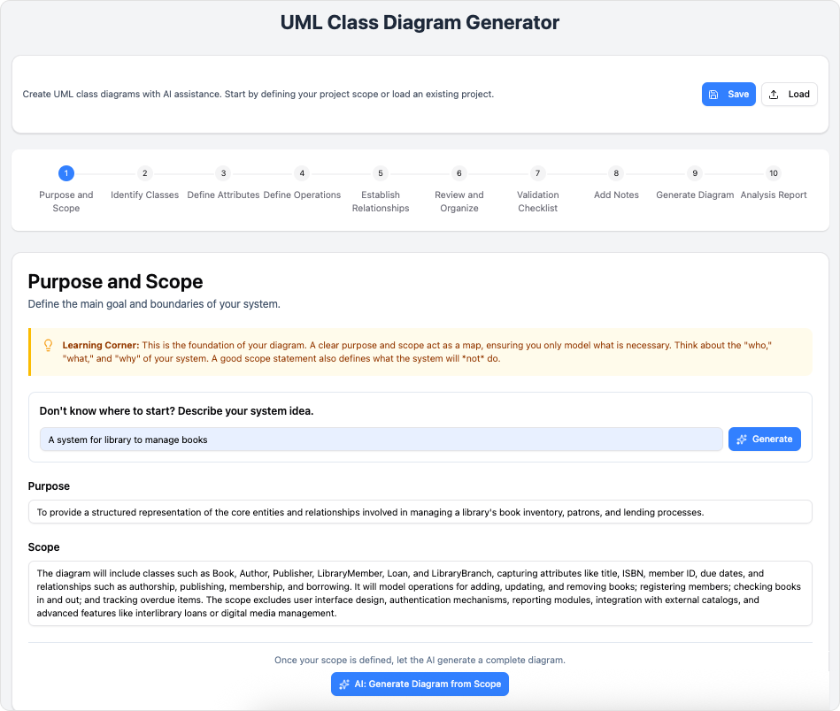
- Step 1: Purpose and Scope
Begin by defining what you are building. You can input a high-level idea (e.g., “Library Management System“) and use the AI-Generate feature to draft a detailed scope. This ensures your project starts with a clear direction. - Step 2: Identify Classes
List the main entities in your system. If you are building an e-commerce site, these would be ‘User’, ‘Product’, ‘Order’, and ‘Cart’. Focus on nouns that represent objects. - Step 3: Define Attributes
For each class, specify the data it holds. Define visibility (public, private) and data types (String, Integer, Boolean) to add precision to your design. - Step 4: Define Operations
List the behaviors or methods for your classes. What can the ‘User’ do? Perhapslogin()orupdateProfile(). This step brings your static classes to life. - Step 5: Establish Relationships
Connect your classes. Define associations, inheritances (Is-A relationships), and compositions (Has-A relationships). This is where the diagram becomes a cohesive system rather than a list of isolated boxes.
Phase 2: Refinement and Validation
Once the structure is in place, the tool guides you through ensuring the design is sound.
- Step 6: Review and Organize
Use the consolidated review screen to see all your inputs in one place. Check for consistency in naming conventions and ensure no orphan classes exist (classes with no relationships). - Step 7: Validation Checklist
Run the automated validation tools. This feature checks for common errors and best practice violations. Address any red flags before proceeding to ensure the final export works correctly. - Step 8: Add Notes
Documentation is key to long-term maintainability. You can manually add clarifications or use the AI to generate summary notes. These notes explain the design rationale, making the diagram useful for educational purposes or team handovers.
Phase 3: Generation and Analysis
The final phase involves rendering the visual output and receiving expert feedback.
- Step 9: Generate Diagram
The tool converts your inputs into raw PlantUML code and renders a scalable SVG diagram. Here, you can preview the visual layout and make final manual edits to the code if you possess the expertise. - Step 10: Analysis Report
This is the most powerful step. Request an AI-powered Analysis Report. The system will critique your architecture, highlighting potential design flaws, coupling issues, or areas for improvement. It provides actionable suggestions to elevate the quality of your software design.
Tips and Tricks
To get the most out of the AI-Assisted UML Class Diagram Generator, consider these optimization strategies:
- Leverage AI for “Writer’s Block”: If you are unsure where to start, type a very simple concept into Step 1 and let the AI generate the scope. You can always edit it later, but it gives you immediate momentum.
- Save Progress as JSON: The tool allows you to save projects in JSON format. Do this regularly. It allows you to back up your work and share the raw data with team members who can load it back into the tool for collaboration.
- Use the Validation Checklist Early: Don’t wait until the very end to check for errors. If you have a complex system, check the validation tab periodically to ensure you aren’t building upon a broken foundation.
- Export for Documentation: Use the SVG export option for high-quality, scalable images suitable for technical documentation, thesis papers, or business presentations.
Checklist for Success
Before finalizing your diagram, ensure you have completed the following actions:
| Action Item | Description |
|---|---|
| Scope Defined | Have you clearly defined the purpose of the system (manually or via AI)? |
| Entities Listed | Are all primary objects represented as Classes? |
| Details Added | Do classes have appropriate Attributes (data) and Operations (methods)? |
| Connections Made | Are relationships (Association, Inheritance, Composition) accurately mapped? |
| Validated | Did you run the Validation Checklist and resolve reported issues? |
| AI Reviewed | Have you generated an Analysis Report to catch architectural flaws? |
| Documentation | Are notes attached to explain complex logic or design choices? |
| Backed Up | Is the project saved locally as a JSON file? |
-
AI-Assisted UML Class Diagram Generator – Visual Paradigm: An interactive, step-by-step tool to help users create UML class diagrams with AI-powered suggestions, validation, PlantUML export, and design analysis.
-
From Problem Description to Class Diagram: AI-Powered Textual Analysis: Explore how Visual Paradigm uses AI to convert natural language problem descriptions into accurate class diagrams for software modeling.
-
How AI Enhances Class Diagram Creation in Visual Paradigm: This blog explores how Visual Paradigm leverages AI to automate and improve the creation of class diagrams, making software design faster and more accurate.
-
Streamlining Class Diagrams with Visual Paradigm’s AI: This article explains how Visual Paradigm’s AI-powered tools reduce the complexity and time required to create accurate class diagrams for software projects.
-
AI-Powered UML Class Diagram Generator by Visual Paradigm: An advanced AI-assisted tool that automatically generates UML class diagrams from natural language descriptions, streamlining software design and modeling.
-
Real-Life Case Study: Generating UML Class Diagrams with Visual Paradigm AI: A detailed case study showcasing how Visual Paradigm’s AI assistant successfully transformed textual requirements into accurate UML class diagrams in a real-world project.
-
Comprehensive Tutorial: Generate UML Class Diagrams with Visual Paradigm’s AI Assistant: Step-by-step guide demonstrating how to use Visual Paradigm Online’s AI assistant to create precise UML class diagrams from plain text input.
-
Creating a UML Class Diagram for a Library System Using AI and Visual Paradigm: A practical blog post that walks through building a UML class diagram for a library management system using Visual Paradigm’s AI assistant.